Mitsubishi Grandis. Manual - part 588


  Index      Mitsubishi     Mitsubishi Grandis - service repair manual


Search            


Content   ..  586  587  588  589   ..


Mitsubishi Grandis. Manual - part 588


DIAGNOSIS

CONTROLLER AREA NETWORK (CAN)

54D-450

terminal No.6

OK: 2 

 or less

CAUTION

Strictly observe the specified wiring harness 
repair procedure. For details refer to 

P.54D-8

.

Q: Are the check results normal?

YES : 

<All the voltages measure 2 V or less> 

Diagnose CAN bus lines thoroughly by 
referring to 

P.54D-16

.

NO : 

<Either or all of the resistances measure 
more than 2 

Ω> Repair the wiring harness 

between joint connector (CAN1) and the 
intermediate connector.

STEP 10. Resistance measurement at A-16 
intermediate connector and C-112 engine-ECU 
<M/T> or engine-A/T-ECU <A/T> connector.

CAUTION

A digital multimeter should be used. For details 
refer to 

P.54D-8

.

CAUTION

The test wiring harness should be used. For 
details refer to 

P.54D-8

.

(1) Disconnect the engine-ECU <M/T> or 

engine-A/T-ECU <A/T> connector and the 
intermediate connector, and measure at the 
wiring harness side.

(2) Ignition switch: OFF (LOCK) 

CAUTION

When measuring the resistance, disconnect the 
negative battery terminal. For details refer to 

P.54D-8

.

(3) Ensure that the negative battery terminal is 

disconnected.

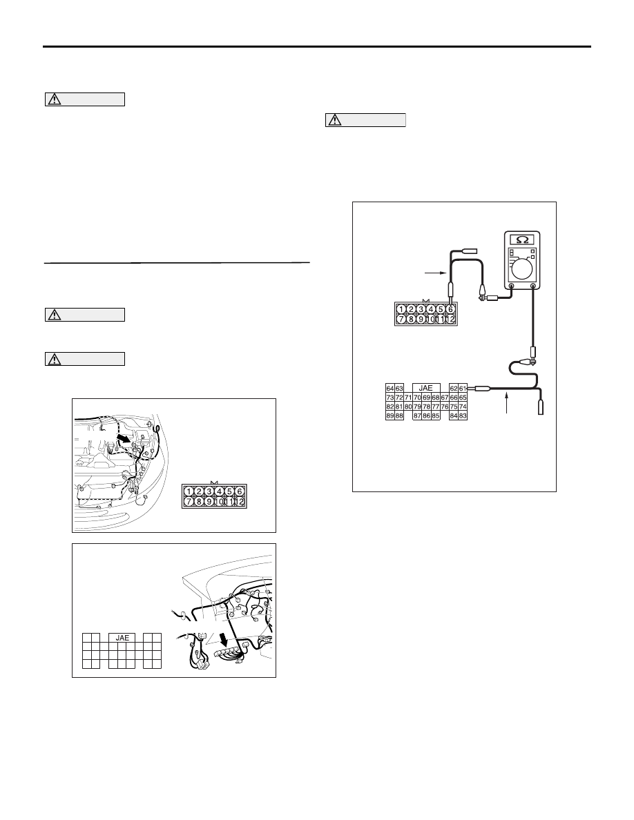
(4) Continuity between A-16 intermediate connector 

terminal No.6 and C-112 engine-ECU <M/T> or 
engine-A/T-ECU <A/T> connector terminal 

AC310398

AC

Connector: A-16 <RHD>

A-16 (B)

AC310628AW

Harness side

Connector: C-112 <RHD>

C-112 (GR)

61

62

63

64

65

66

67

68

69

70

71

72

73

74

75

76

77

78

79

80

81

82

83

84

85

86

87

88

89

AC312553

Harness side: C-112

Test
harness

AS

Male side: A-16

Test
harness

DIAGNOSIS

CONTROLLER AREA NETWORK (CAN)

54D-451

No.61.

OK: 2 

 or less

(5) Continuity between A-16 intermediate connector 

terminal No.12 and C-112 engine-ECU <M/T> or 
engine-A/T-ECU <A/T> connector terminal 
No.62.

OK: 2 

 or less

CAUTION

Strictly observe the specified wiring harness 
repair procedure. For details refer to 

P.54D-8

.

Q: Are the check results normal?

YES : 

<All the voltages measure 2 

Ω or less> Go 

to Step 11  .

NO : 

<Either or all of the resistances measure 
more than 2 

Ω> Repair the wiring harness 

between the engine-ECU <M/T> or 
engine-A/T-ECU <A/T> connector and the 
intermediate connector.

STEP 11. Resistance measurement at C-112 
engine-ECU <M/T> or engine-A/T-ECU <A/T> 
connector.

CAUTION

A digital multimeter should be used. For details 
refer to 

P.54D-8

.

(1) Remove the engine-ECU <M/T> or 

engine-A/T-ECU <A/T>, and measure at the 
equipment side.

(2) Resistance at C-112 engine-ECU <M/T> or 

engine-A/T-ECU <A/T> connector terminal Nos. 
61 and 62

OK: 120

± 20 

Q: Is the check result normal?

YES : 

<120

± 20 within Ω> Diagnose CAN bus 

lines thoroughly. Refer to 

P.54D-16

.

NO : 

<120

± 20 Ω not within> Replace the 

engine-ECU <M/T> or engine-A/T-ECU 
<A/T>.

AC312553

Harness side: C-112

Test
harness

AT

Test
harness

Male side: A-16

AC310628AW

Harness side

Connector: C-112 <RHD>

C-112 (GR)

61

62

63

64

65

66

67

68

69

70

71

72

73

74

75

76

77

78

79

80

81

82

83

84

85

86

87

88

89

AC312553

Equipment side: C-112

Test
harness

AC

Test
harness

DIAGNOSIS

CONTROLLER AREA NETWORK (CAN)

54D-452

Diagnostic Item 17: Diagnose CAN bus lines thoroughly <LH drive vehicles without ASC>

CAUTION

When servicing a CAN bus line, earth yourself by 
touching a metal object such as an unpainted 
water pipe. If you fail to do, a component 
connected to the CAN bus line may be broken.

A/C-ECU

CENTER DISPLAY

COMBINATION
METER

DIAGNOSIS
CONNECTOR

ABS-ECU

ENGINE-ECU<M/T>
ENGINE·A/T-ECU<A/T>

Wire colour code
B : Black     LG : Light green     G : Green     L : Blue     W : White     Y : Yellow     SB : Sky blue
BR : Brown     O : Orange     GR : Gray     R : Red     P : Pink     V : Violet

DIAGNOSIS

CONTROLLER AREA NETWORK (CAN)

54D-453

TROUBLE JUDGMENT

If the MUT-III can not received signals from ECUs, 
CAN bus line connector(s) are broken or an open 
circuit has occurred.

COMMENTS ON TROUBLE SYMPTOM

The CAN bus line wire or connectors may have 
loose, corroded, or damage terminals, or terminals 
pushed back in the connector.

POSSIBLE CAUSES

• Damaged harness wires and connectors

• Malfunction of the ETACS-ECU

• Malfunction of the combination meter

• Malfunction of the A/C-ECU

• Malfunction of the SRS-ECU

• Malfunction of the multi-centre display

• Malfunction of the ABS-ECU

• Malfunction of the engine-ECU <M/T> or 

engine-A/T-ECU <A/T>

DIAGNOSTIC PROCEDURE

STEP 1. Connector check: C-126 diagnosis 
connector

CAUTION

The strand end of the twist wire should be within 
10 cm from the connector. For details refer to 

P.54D-8

.

Q: Is the check result normal?

YES : 

Go to Step 2 .

NO : 

Repair the defective connector.

ETACS-ECU

SRS-ECU

Wire colour code
B : Black     LG : Light green     G : Green     L : Blue     W : White     Y : Yellow     SB : Sky blue
BR : Brown     O : Orange     GR : Gray     R : Red     P : Pink     V : Violet

AC310613

AO

Connector: C-126 <LHD>

Harness side 
(Front side)

C-126 (B)


Content   ..  586  587  588  589   ..