Mitsubishi Grandis. Manual - part 571
DIAGNOSIS
CONTROLLER AREA NETWORK (CAN)
54D-382
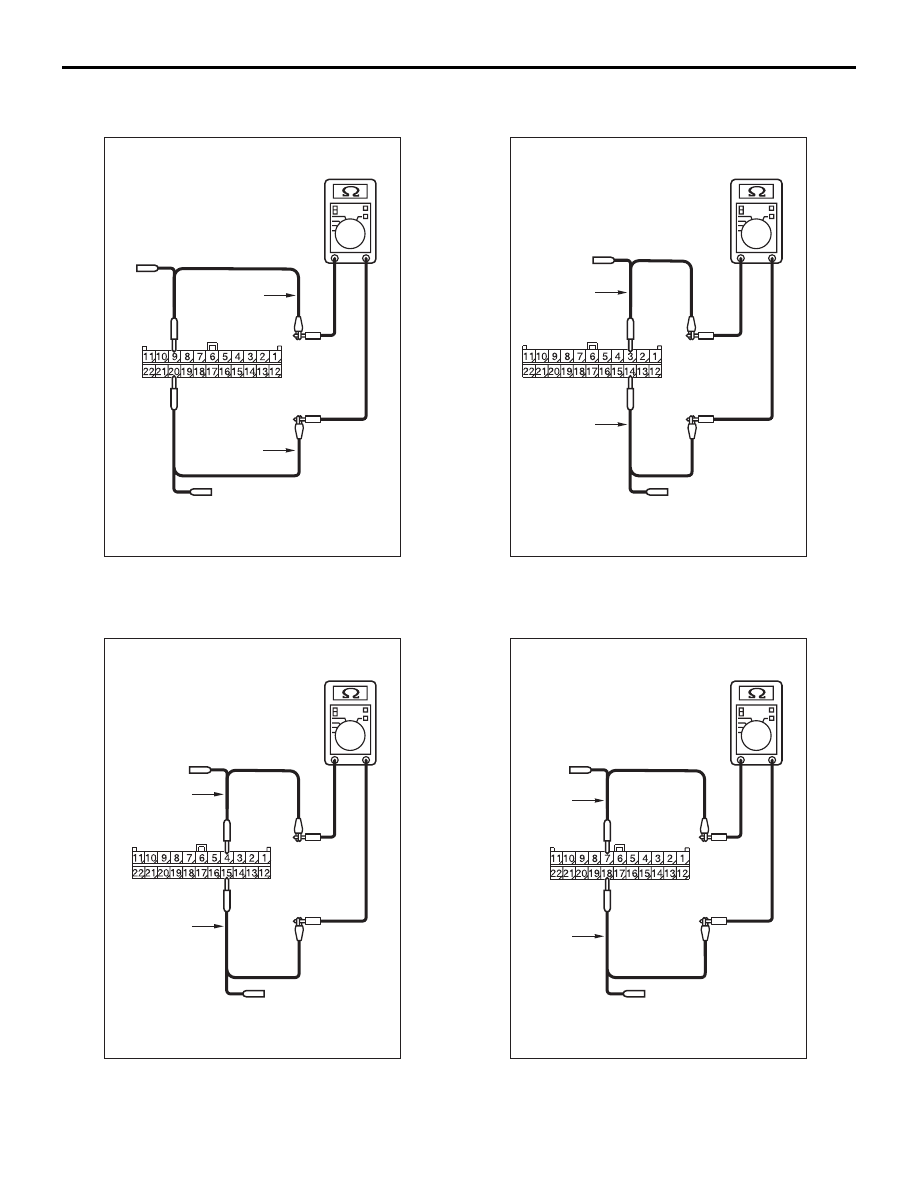
terminal Nos. 5 and 16
OK: 1 k
Ω or more
(7) Resistance between C-09 joint connector (CAN2)
terminal Nos. 9 and 20
OK: 1 k
Ω or more
(8) Resistance between C-09 joint connector (CAN2)
terminal Nos. 4 and 15
OK: 1 k
Ω or more
(9) Resistance between C-09 joint connector (CAN2)
terminal Nos. 3 and 14
OK: 1 k
Ω or more
(10)Resistance between C-09 joint connector
AC204740DP
Harness side: C-09
Test
harness
Test
harness
AC204740DQ
Harness side: C-09
Test
harness
Test
harness
AC204740DF
Harness side: C-09
Test
harness
Test
harness
AC204740DD
Harness side: C-09
Test
harness
Test
harness