Mitsubishi Grandis. Manual - part 552
DIAGNOSIS
CONTROLLER AREA NETWORK (CAN)
54D-306
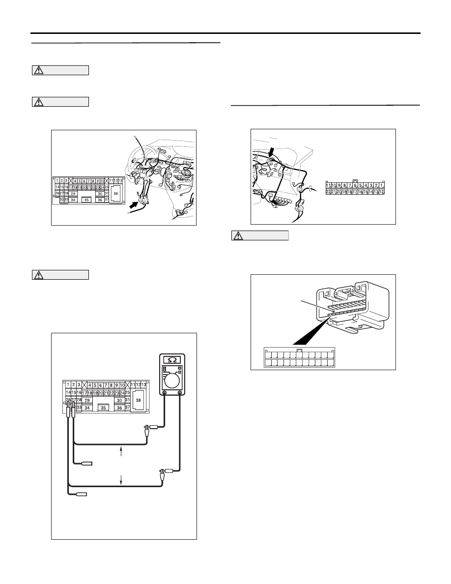
STEP 2. Resistance measurement at the C-125
intermediate connector.
CAUTION
A digital multimeter should be used. For details
refer to
CAUTION
The test wiring harness should be used. For
details refer to
(1) Disconnect the connector, and measure at its
male-side intermediate connector (at the front
wiring harness side).
(2) Ignition switch: OFF (LOCK)
CAUTION
When measuring the resistance, disconnect the
negative battery terminal. For details refer to
(3) Ensure that the negative battery terminal is
disconnected.
(4) Resistance between C-125 intermediate
connector terminal Nos.26 and 27
OK: 120
± 20 Ω
Q: Is the check result normal?
YES :
<Within 120
± 20 Ω> Go to Step 3 .
NO :
<Not within 120
± 20 Ω> Go to Step 26 .
STEP 3. Connector check: C-09 joint connector
(CAN2)
CAUTION
The strand end of the twist wire should be within
10 cm from the connector. For details refer to
When checking the joint connector, ensure that its
wiring harness side and its short pins are not
damaged.
Q: Is the check result normal?
YES :
Go to Step 4.
NO :
Repair a defective connector or replace the
joint connector.
AC310613
AD
Connector: C-125 <LHD>
AC204740
AC204740
AC204740
AC204740
AC204740DC
Male side: C-125
Test
harness
AC310615
AU
Harness side
Connector: C-09 <LHD>
C-09 (GR)
AC209350
1
12
2
13
3
14
4
15
5
16
6
17
7
18
8
19
9
20
10
21
11
22
AB
Short pin