Mitsubishi Grandis. Manual - part 519
DIAGNOSIS
CONTROLLER AREA NETWORK (CAN)
54D-174
TROUBLE JUDGMENT
The CAN bus line has been shorted to earth if the
voltage between the CAN bus line (CAN_L or
CAN_H) and body earth is less than 1.0 V. In this
condition, an abnormal voltage may be measured at
CAN_L and CAN_H lines.
COMMENTS ON TROUBLE SYMPTOM
The wiring harness wire or connectors may have
loose, corroded, or damage terminals, or terminals
pushed back in the connector, or a ECU may be
defective.
POSSIBLE CAUSES
• Damaged harness wires and connectors
• Malfunction of the ETACS-ECU
• Malfunction of the combination meter
• Malfunction of the A/C-ECU
• Malfunction of the SRS-ECU
• Malfunction of the multi-centre display
• Malfunction of the ABS-ECU
• Malfunction of the engine-ECU <M/T> or
engine-A/T-ECU <A/T>
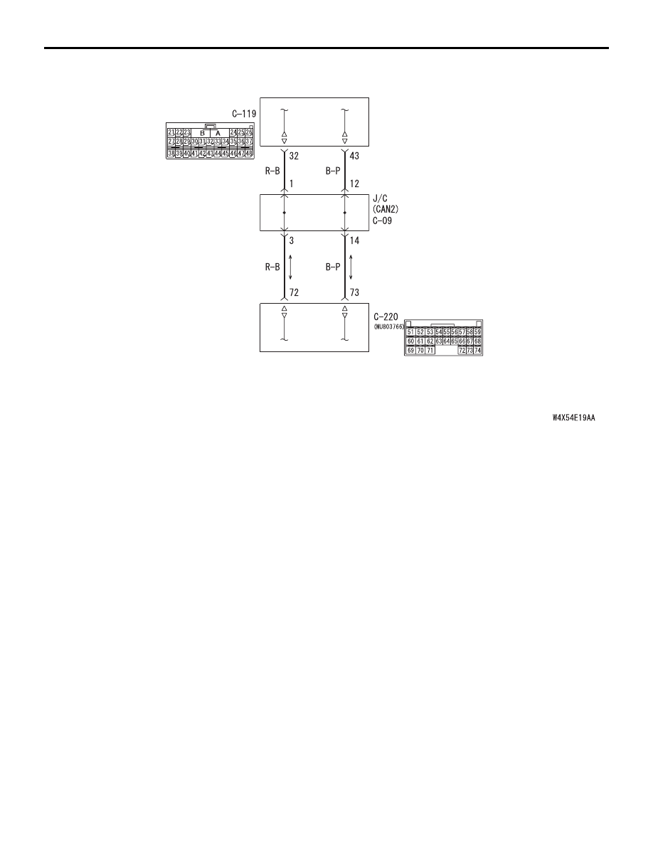
ETACS-ECU
SRS-ECU
Wire colour code
B : Black LG : Light green G : Green L : Blue W : White Y : Yellow SB : Sky blue
BR : Brown O : Orange GR : Gray R : Red P : Pink V : Violet