Mitsubishi Grandis. Manual - part 501


  Index      Mitsubishi     Mitsubishi Grandis - service repair manual


Search            


Content   ..  499  500  501  502   ..


Mitsubishi Grandis. Manual - part 501


DIAGNOSIS

CONTROLLER AREA NETWORK (CAN)

54D-102

No.4 and body earth

OK: Less than 1.0 V

(4) Disconnect the negative battery terminal.

CAUTION

Strictly observe the specified wiring harness 
repair procedure. For details refer to 

P.54D-8

.

Q: Is the check result normal?

YES : 

<less than 1.0 V> Follow diagnostic item 18 

"Diagnose CAN bus lines thoroughly." Refer 
to 

P.54D-476

.

NO : 

<1.0 V or more> Repair the wiring harness 
between the jumper connector and the 
centre display connector.

STEP 43. Connector check: C-119 SRS-ECU 
connector

CAUTION

The strand end of the twist wire should be within 
10 cm from the connector. For details refer to 

P.54D-8

.

Q: Is the check result normal?

YES : 

Go to Step 44 .

NO : 

Repair the defective connector.

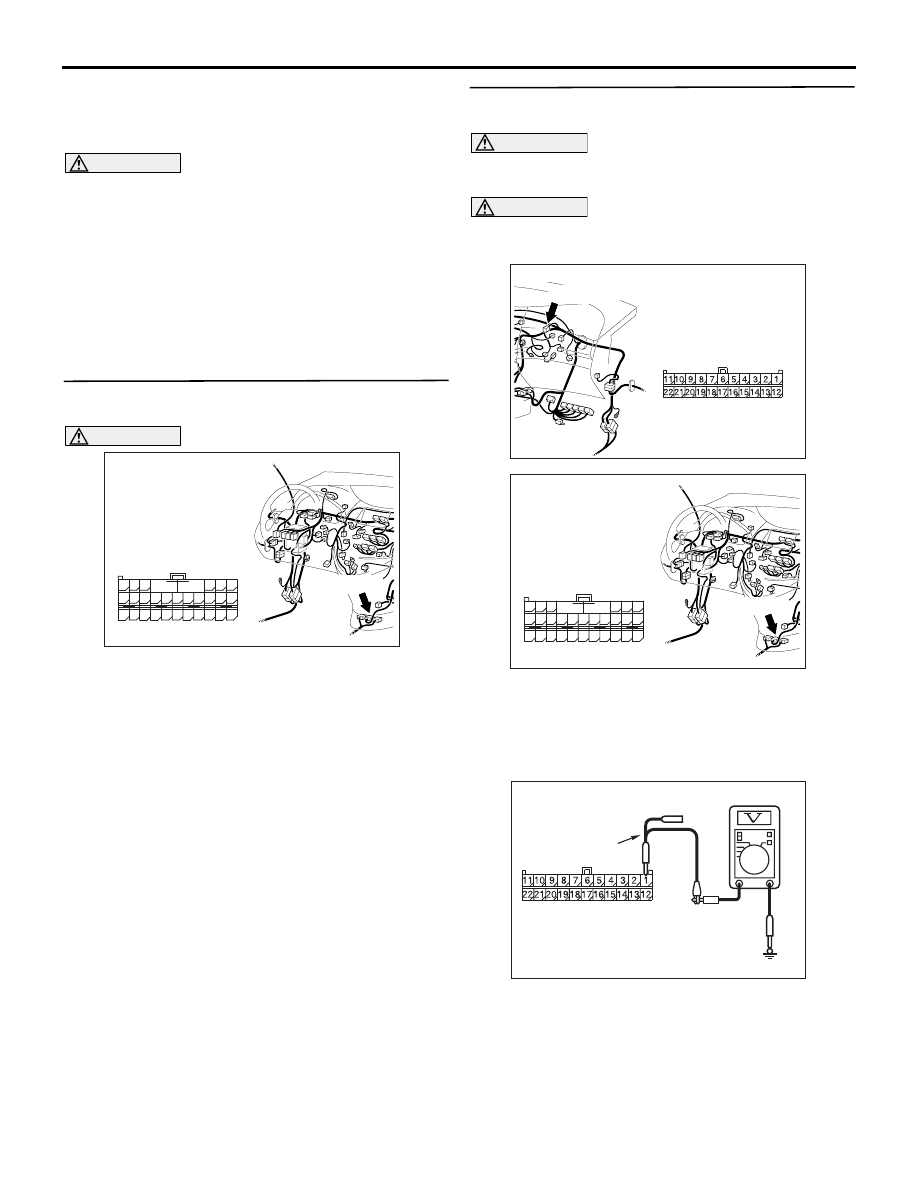
STEP 44. Voltage measurement at C-09 joint 
connector (CAN2).

CAUTION

A digital multimeter should be used. For details 
refer to 

P.54D-8

.

CAUTION

The test wiring harness should be used. For 
details refer to 

P.54D-8

.

(1) Disconnect the joint connector (CAN2) and the 

SRS-ECU connector, and measure at the wiring 
harness side.

(2) Connect the negative battery terminal, and turn 

the ignition switch to the ON position.

(3) Voltage between C-09 joint connector (CAN2) 

AC310613

BD

Connector: C-119 
<LHD>

Harness side

C-119 (Y)

48

37

26

42

31

45

34

47

36

46

35

44

33

43

32

25 24

39

28

41

30

40

29

38

27

23

21

22

A

B

AC310615

AU

Harness side

Connector: C-09 <LHD>

C-09 (GR)

AC310613

BD

Connector: C-119 
<LHD>

Harness side

C-119 (Y)

48

37

26

42

31

45

34

47

36

46

35

44

33

43

32

25 24

39

28

41

30

40

29

38

27

23

21

22

A

B

AC209365KK

Harness side: C-09

Test
harness

DIAGNOSIS

CONTROLLER AREA NETWORK (CAN)

54D-103

terminal No.1 and body earth

OK: Less than 1.0 V

(4) Disconnect the negative battery terminal.

CAUTION

Strictly observe the specified wiring harness 
repair procedure. For details refer to 

P.54D-8

.

Q: Is the check result normal?

YES : 

<less than 1.0 V> Follow diagnostic item 18 

"Diagnose CAN bus lines thoroughly." Refer 
to 

P.54D-476

.

NO : 

<1.0 V or more> Repair the wiring harness 
between the joint connector (CAN2) and the 
SRS-ECU connector.

STEP 45. Connector check: C-306 steering wheel 
angle sensor connector

CAUTION

The strand end of the twist wire should be within 
10 cm from the connector. For details refer to 

P.54D-8

.

Q: Is the check result normal?

YES : 

Go to Step 46 .

NO : 

Repair the defective connector.

STEP 46. Voltage measurement at C-09 joint 
connector (CAN2).

CAUTION

A digital multimeter should be used. For details 
refer to 

P.54D-8

.

CAUTION

The test wiring harness should be used. For 
details refer to 

P.54D-8

.

(1) Disconnect the joint connector (CAN2) and the 

steering wheel angle sensor connector, and 
measure at the wiring harness side.

(2) Connect the negative battery terminal, and turn 

the ignition switch to the ON position.

(3) Voltage between C-09 joint connector (CAN2) 

AC310153AF

Connector: C-306 <LHD>

Harness side

AC310615

AU

Harness side

Connector: C-09 <LHD>

C-09 (GR)

AC310153AF

Connector: C-306 <LHD>

Harness side

AC209365KR

Harness side: C-09

Test harness

DIAGNOSIS

CONTROLLER AREA NETWORK (CAN)

54D-104

terminal No.8 and body earth

OK: Less than 1.0 V

(4) Disconnect the negative battery terminal.

CAUTION

Strictly observe the specified wiring harness 
repair procedure. For details refer to 

P.54D-8

.

Q: Is the check result normal?

YES : 

<less than 1.0 V> Follow diagnostic item 18 

"Diagnose CAN bus lines thoroughly." Refer 
to 

P.54D-476

.

NO : 

<1.0 V or more> Repair the wiring harness 
between the joint connector (CAN2) and the 
steering wheel angle sensor connector.

STEP 47. Voltage measurement at C-09 joint 
connector (CAN2).

CAUTION

A digital multimeter should be used. For details 
refer to 

P.54D-8

.

CAUTION

The test wiring harness should be used. For 
details refer to 

P.54D-8

.

(1) Disconnect the connector, and measure at the 

wiring harness side.

(2) Connect the negative battery terminal, and turn 

the ignition switch to the ON position.

(3) Voltage between C-09 joint connector (CAN2) 

terminal No.6 and body earth

OK: Less than 1.0 V

(4) Disconnect the negative battery terminal.

CAUTION

Strictly observe the specified wiring harness 
repair procedure. For details refer to 

P.54D-8

.

Q: Is the check result normal?

YES : 

<less than 1.0 V> Follow diagnostic item 18 

"Diagnose CAN bus lines thoroughly." Refer 
to 

P.54D-476

.

NO : 

<1.0 V or more> Repair the wiring harness 
between the joint connector (CAN2) and the 
diagnosis connector.

STEP 48. Voltage measurement at C-09 joint 
connector (CAN2).

CAUTION

A digital multimeter should be used. For details 
refer to 

P.54D-8

.

CAUTION

The test wiring harness should be used. For 
details refer to 

P.54D-8

.

(1) Disconnect the connector, and measure at the 

wiring harness side.

(2) Connect the negative battery terminal, and turn 

the ignition switch to the ON position.

(3) Voltage between C-09 joint connector (CAN2) 

AC310615

AU

Harness side

Connector: C-09 <LHD>

C-09 (GR)

AC209365KL

Harness side: C-09

Test harness

AC310615

AU

Harness side

Connector: C-09 <LHD>

C-09 (GR)

AC209365KN

Harness side: C-09

Test
harness

DIAGNOSIS

CONTROLLER AREA NETWORK (CAN)

54D-105

terminal No.4 and body earth

OK: Less than 1.0 V

(4) Disconnect the negative battery terminal.

CAUTION

Strictly observe the specified wiring harness 
repair procedure. For details refer to 

P.54D-8

.

Q: Is the check result normal?

YES : 

<less than 1.0 V> Follow diagnostic item 18 

"Diagnose CAN bus lines thoroughly." Refer 
to 

P.54D-476

.

NO : 

<1.0 V or more> Repair the wiring harness 
between the joint connector (CAN2) and the 
intermediate connector.

STEP 49. Connector check: A-07 joint connector 
(CAN1)
NOTE: When checking A-07 joint connector (CAN1), 
disassemble and check the engine compartment 
relay box by referring to 

P.54D-616

.

CAUTION

The strand end of the twist wire should be within 
10 cm from the connector. For details refer to 

P.54D-8

.

When checking the joint connector, ensure that its 
wiring harness side is not damaged.

Q: Is the check result normal?

YES : 

Go to Step 50 .

NO : 

Repair a defective connector or replace the 
joint connector (front wiring harness 
assembly).

STEP 50. Voltage measurement at the A-07 joint 
connector (CAN1).
NOTE: When checking A-07 joint connector (CAN1), 
disassemble and check the engine compartment 
relay box by referring to 

P.54D-616

.

CAUTION

A digital multimeter should be used. For details 
refer to 

P.54D-8

.

CAUTION

The test wiring harness should be used. For 
details refer to 

P.54D-8

.

(1) Disconnect the connector, and measure at the 

wiring harness side.

(2) Connect the negative battery terminal, and turn 

the ignition switch to the ON position.

(3) Voltage between A-07 joint connector (CAN1) 

terminal No.6 and body earth

OK: 4.0 V or less

(4) Voltage between A-07 joint connector (CAN1) 

AC302572AD

Connector: A-07

Harness side

AC302572AD

Connector: A-07

Harness side

AC209365KG

Harness side: A-07

Test harness

AC209365KM

Harness side: A-07

Test harness


Content   ..  499  500  501  502   ..