Mitsubishi Grandis. Manual - part 486
DIAGNOSIS
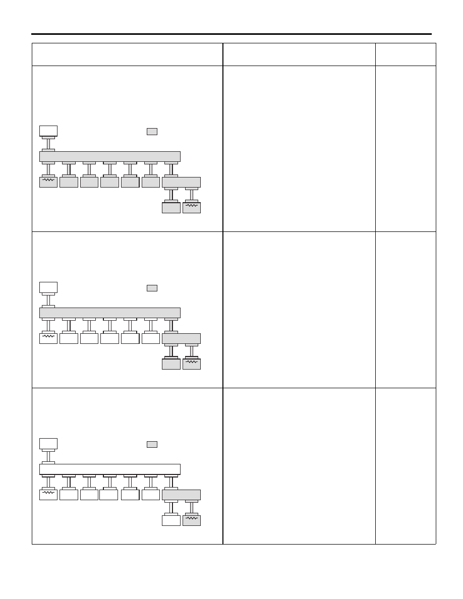
CONTROLLER AREA NETWORK (CAN)
54D-42
<Comment>
Malfunction in red displayed area is estimated.
Please refer to service manual and inspect with
’CAN Detail
Diagnosis’.
Diagnostic Item 20
Diagnose CAN bus lines thoroughly
<RH drive vehicles with ASC>
<Comment>
Harness disconnection or loose connection in red
displayed area is
estimated.
Diagnostic Item 22
Diagnose the lines between the joint
connectors (CAN1 and CAN2) <RH
drive vehicles>
<Comment>
Harness disconnection or loose connection in red
displayed area is
estimated.
Diagnostic Item 23
Diagnose the lines from the main bus
line to the engine-ECU <M/T> or
engine-A/T-ECU <A/T>.
MUT-III SCREEN
DIAGNOSIS DETAILS
REFERENCE
PAGE
AC309835
: Red section
on screen
MUT
J/C (2)
METER
ETACS
J/C (1)
ASC-ECU
ENG/AT-ECU
C. DISPLAY
A/C-ECU
STR. A.
SNSR
SRS-ECU
AC
AC309835
: Red section
on screen
MUT
J/C (2)
METER
ETACS
J/C (1)
ASC-ECU
ENG/AT-ECU
C. DISPLAY
A/C-ECU
STR. A.
SNSR
SRS-ECU
AE
AC309835
: Red section
on screen
MUT
J/C (2)
METER
ETACS
J/C (1)
ASC-ECU
ENG/AT-ECU
C. DISPLAY
A/C-ECU
STR. A.
SNSR
SRS-ECU
AJ