Mitsubishi Grandis. Manual - part 477
SPECIAL TOOL
CONTROLLER AREA NETWORK (CAN)
54D-6
Tool
Number
Name
Use
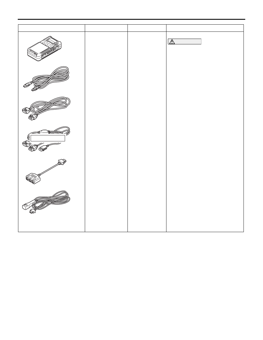
MB991955
A: MB991824
B: MB991827
C: MB991910
D: MB991911
E: MB991825
F: MB991826
MUT-III
sub-assembly
A: Vehicle
Communication
Interface (V.C.I.)
B: MUT-III USB
cable
C: MUT-III main
harness A
(Vehicles with
CAN
communication
system)
D: MUT-III main
harness B
(Vehicles without
CAN
communication
system)
E: MUT-III
measure adapter
F: MUT-III trigger
harness
CAN bus diagnostics
CAUTION
For vehicles with CAN
communication, use MUT-III main
harness A to send simulated
vehicle speed. If you connect
MUT-III main harness B instead,
the CAN communication does
not function correctly.
MB991910
MB991826
MB991955
MB991911
MB991824
MB991827
MB991825
A
B
C
D
E
F
DO NOT USED