Mitsubishi Grandis. Manual - part 423
CENTRALIZED JUNCTION
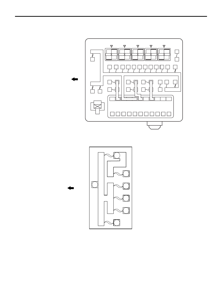
CIRCUIT DIAGRAMS
90-13
PASSENGER COMPARTMENT
AC208462
Front of vehicle
(Relay box in engine compartment)
1
6
7
8
9 10 11 12 13 14 15
25
4
2
3
16
17
18
19
20
21
23 22
5
AV
24
AC304080
Front of vehicle
28
29
27
26
30
31
AD
(Fusible link box in engine compartment)