Mitsubishi Grandis. Manual - part 394
FRONT AXLE HUB ASSEMBLY
FRONT AXLE
26-8
FRONT AXLE HUB ASSEMBLY
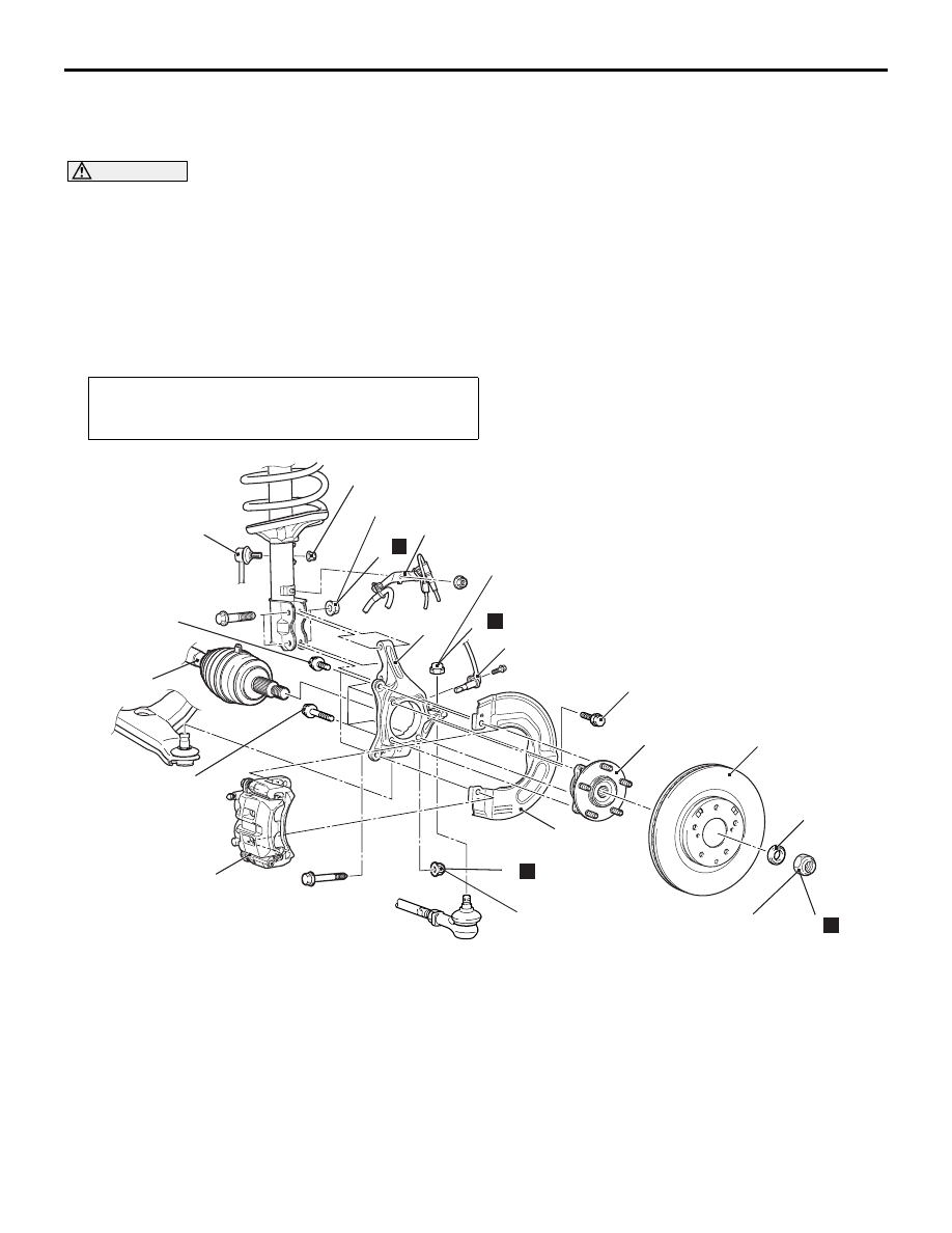
REMOVAL AND INSTALLATION
M1261001700450
CAUTION
• Do not disassemble the front wheel hub assembly.
• The vehicle speed detection magnetic encoder collects any metallic particle easily, because it is
magnetised. Make sure that the magnetic encoder should not collect any metallic particle. Check
that there is not any trouble prior to reassembling it.
• When the front wheel hub assembly is removed and installed, make sure that the vehicle speed
detection magnetic encoder does not contact with surrounding parts to avoid damage.
• When the front wheel speed sensor is removed and installed, make sure that its pole piece does
not contact with surrounding parts to avoid damage.
Post-installation Operation
• Check the dust cover for cracks or damage by pushing it
with your finger.
AC311040
N
7
4
1
9
13
80 ± 10 N·m
29 ± 4 N·m
108 ± 10 N·m
245 ± 29 N·m
80 ± 10 N·m
AC
12
14
11
8
100 ± 10 N·m
N
9.0 ± 2.0 N·m
10
3
2
6
5
89 ± 9 N·m
N
N
Removal
steps
<<A>> >>A<<
1. Drive shaft nut
>>A<<
2. Washer
3. Front wheel speed sensor
4. Brake
hose
bracket
5. Stabilizer link connection
<<B>>
6. Caliper assembly
<<C>>
7. Brake disc
8. Self-locking nut (lower arm ball joint
connection)
<<D>>
9. Self-locking nut (tie rod end
connection)
<<E>>
10. Drive shaft
11. Nut (hub and knuckle to strut
connection)
12. Knuckle
13. Front wheel hub assembly
14. Dust cover
Removal
steps
(Continued)