Mitsubishi Grandis. Manual - part 328


  Index      Mitsubishi     Mitsubishi Grandis - service repair manual


Search            


Content   ..  326  327  328  329   ..


Mitsubishi Grandis. Manual - part 328


ON-VEHICLE SERVICE

HEATER, AIR CONDITIONER AND VENTILATION

55-197

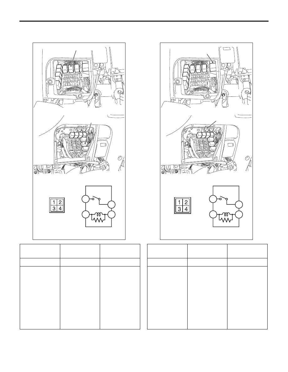
FRONT BLOWER LELAY CONTINUITY 
CHECK

PTC HEATER RELAY 1 CONTINUITY 
CHECK

Battery voltage Tester 

connection

Specified 
condition

Not applied

− 5

Open circuit

• Connect 

terminal 3 to 
the positive 
battery 
terminal

• Connect 

terminal 1 to 
the negative 
battery 
terminal

− 5

Less than 2 
ohms

AC312183

<LHD>

<RHD>

Front blower relay

5

4

3

1

AC

Front blower relay

Battery voltage Tester 

connection

Specified 
condition

Not applied

− 5

Open circuit

• Connect 

terminal 3 to 
the positive 
battery 
terminal

• Connect 

terminal 1 to 
the negative 
battery 
terminal

− 5

Less than 2 
ohms

AC312183

<LHD>

<RHD>

PTC heater relay 1

5

4

3

1

AD

PTC heater relay 1

ON-VEHICLE SERVICE

HEATER, AIR CONDITIONER AND VENTILATION

55-198

PTC HEATER RELAY 2 CONTINUITY 
CHECK

IDLE-UP OPERATION CHECK

M1552001600456

1. Before inspection and adjustment, set vehicle in 

the following condition:

• Engine coolant temperature: 80 − 90 °C

• Lamps, electric cooling fan and accessories: Set 

to OFF

• Transmission: Neutral ("N" or "P" for vehicles with 

A/T)

• Steering wheel: Straightforward

2. Check whether or not the idle speed is the 

standard value.
Refer to GROUP 11A, On-vehicle Service 

− Basic 

Idle Speed Adjustment 

P.11A-12

.

Standard value:
750 

± 50 r/min

3. When the A/C is running after turning the A/C 

switch to ON, and the blower switch to the 3(MH) 
or 4(HI) position, check to be sure that the idle 
speed is at the standard value.

Standard value: 850 

± 50 r/min

NOTE: It is not necessary to make an adjustment, 
because the idling speed is automatically 
adjusted by the ISC system. If, however, a 
deviation from the standard value occurs for some 
reason, check the ISC system.

CLEAN AIR FILTER REPLACEMENT 
PROCEDURE

M1552020600024

1. Remove the glove box. (Refer to GROUP 52A, 

Instrument Panel 

P.52A-2

.)

2. Remove the two screws as shown, and replace 

the clean air filter.

3. Install the glove box.

Battery voltage Tester 

connection

Specified 
condition

Not applied

− 5

Open circuit

• Connect 

terminal 3 to 
the positive 
battery 
terminal

• Connect 

terminal 1 to 
the negative 
battery 
terminal

− 5

Less than 2 
ohms

AC312183

<LHD>

<RHD>

PTC heater relay 2

5

4

3

1

AE

PTC heater relay 2

AC311467AB

HEATER CONTROL UNIT

HEATER, AIR CONDITIONER AND VENTILATION

55-199

HEATER CONTROL UNIT

REMOVAL AND INSTALLATION

M1554014700051

INSPECTION

M1552014301362

REAR FAN SWITCH CONTINUITY CHECK

Pre-removal and Post-installation Operation
• Instrument centre panel Removal and Installation (Refer 

to GROUP 52A, Instrument Panel 

P.52A-2

.)

AC310128

1

2

6

4

5

3

7

AB

Removal steps

1.

Rear fun switch

2.

Heater control lever knob

3.

Automatic air conditioner control 
panel (A/C-ECU)

4.

Defogger switch knob

5.

Inside/outside air selection switch 
knob

6.

Panel

7.

Instrument centre panel

Switch 
position

Tester connection  Specified 

condition

OFF

− 2

Open circuit

ON

Less than 2 ohms

AC310127

HEATER UNIT AND BLOWER ASSEMBLY

HEATER, AIR CONDITIONER AND VENTILATION

55-200

HEATER UNIT AND BLOWER ASSEMBLY

REMOVAL AND INSTALLATION

M1552020800028

REMOVAL SERVICE POINTS
<<A>> CONNECTOR DISCONNECTION

Disconnect the following connectors to remove the 
front deck crossmember and the heater unit 
assembly.

Pre-removal Operation
• Engine coolant Draining (Refer to 

P.14-17

.)

• Refrigerant draining (Refer to 

P.55-190

.)

• Air cleaner Removal (Refer to GROUP 15, Air Cleaner 

P.15-3

.)

• Front seat assembly Removal (Refer to GROUP 52A, 

Front Seat Assembly 

P.52A-21

.)

• Rear heater duct Removal (Refer to Duct 

P.55-227

.)

• Instrument panel Removal (Refer to GROUP 52A, 

Instrument Panel 

P.52A-2

.)

• SRS-ECU Removal (Refer to GROUP 52B, SRS Air Bag 

P.52B-223

.)

Post-installation Operation
• Adjust the front air mix damper control motor. (Refer to 

P.55-206

.)

• SRS-ECU Installation (Refer to GROUP 52B, SRS Air 

Bag 

P.52B-223

.)

• Instrument panel Installation (Refer to GROUP 52A, 

Instrument Panel 

P.52A-2

.)

• Rear heater duct Removal (Refer to Duct 

P.55-227

.)

• Front seat assembly Installation (Refer to GROUP 52A, 

Front Seat Assembly 

P.52A-21

.)

• Air cleaner Installation (Refer to GROUP 15,Air Cleaner 

P.15-3

.)

• Engine coolant Refilling (Refer to 

P.14-17

.)

• Refrigerant Refilling (Refer to 

P.55-191

.)

AC310129AC

1

2

3

4

N

6

2, 3

A/C compressor oil:
  SUN PAG 56

-Pipe coupling

O ring

5

32 ± 2 N·m

Removal steps

<<A>>

Harness and clamp

Junction block installation

1.

Heater hose

Canister installation

<<B>>

2.

Suction pipe

<<B>>

3.

Liquid pipe B

4.

O ring

5.

Drain hose

6.

Front deck cross member heater 
unit assembly


Content   ..  326  327  328  329   ..