Mitsubishi Grandis. Manual - part 302


  Index      Mitsubishi     Mitsubishi Grandis - service repair manual


Search            


Content   ..  300  301  302  303   ..


Mitsubishi Grandis. Manual - part 302


TROUBLESHOOTING

HEATER, AIR CONDITIONER AND VENTILATION

55-93

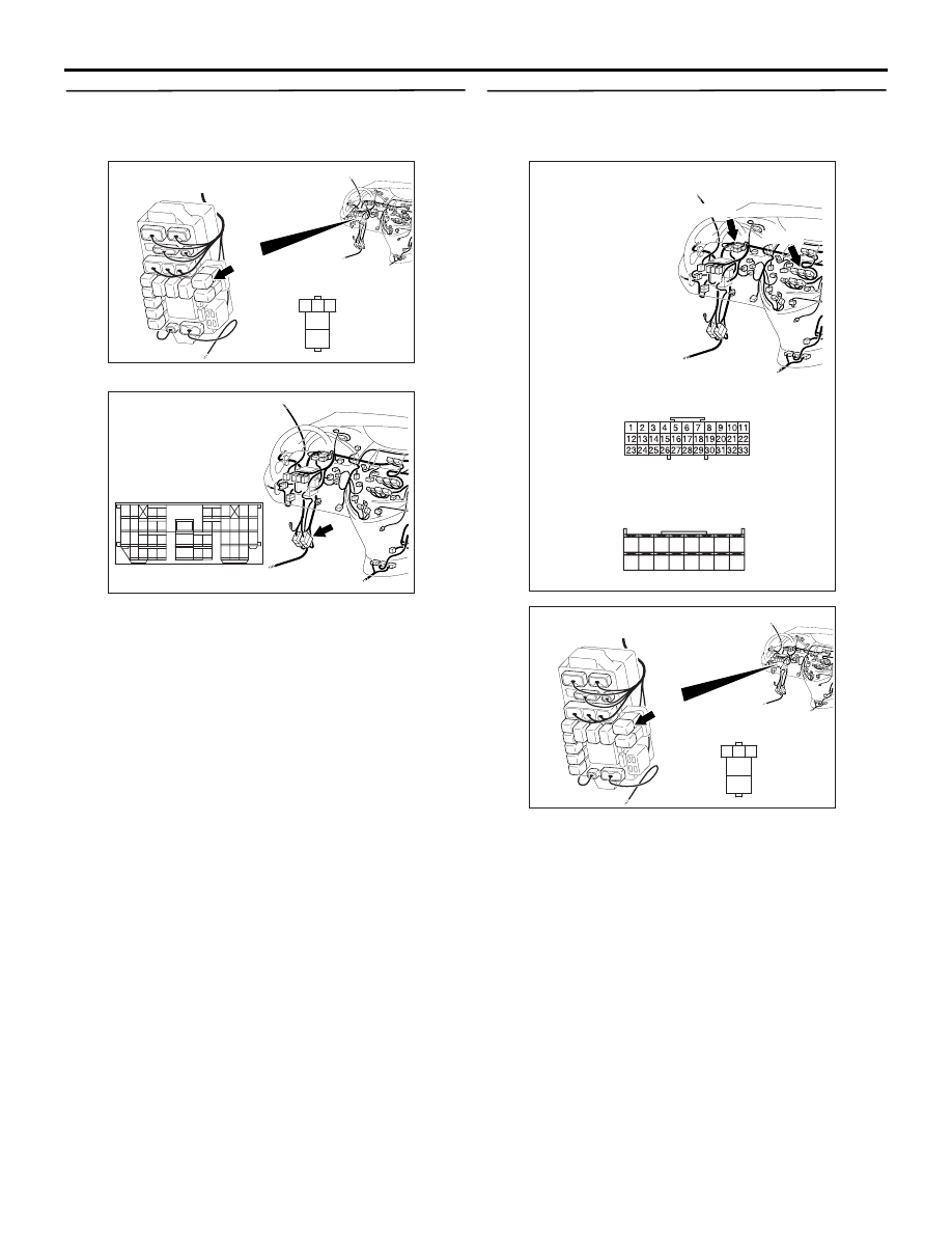
Step 16. Check the wiring harness between C-206 
PTC heater relay 1 connector terminal No.4 and 
the fusible link (28).

NOTE: 

Prior to the wiring harness inspection, check 
intermediate connector C-124, and repair if 
necessary.

• Check the PTC heater relay 1 power supply line 

for open circuit.

Q: Is the check result normal?

YES : 

The trouble can be an intermittent 

malfunction (Refer to GROUP 00, How to 
Cope with Intermittent Malfunction 

P.00-5

).

NO : 

Repair the wiring harness.

Step 17. Check the wiring harness between C-206 
PTC heater relay 1 connector terminal No.1 and 
C-105 A/C-ECU connector terminal No.46.

NOTE: Prior to the wiring harness inspection, check 
joint connector C-01, and repair if necessary.

• Check the PTC heater relay 1 earth line for open 

or short circuit.

Q: Is the check result normal?

YES : 

 Go to Step 18.

NO : 

Repair the wiring harness.

AC310623

Connector: C-206 <LHD>

AE

3

4

5

1

2

Junction block side

Junction block (Front view)

AC310613

AH

Connector: C-124 <LHD>

9

21

33

35

24

12

3 4

7

8

5 6

39

28

41

30

18

4243

31

1920

32

40

29

1617

38

27

15

37

36

26

14

13

25

2

1

34

23

11

10

22

AC310614

BB

Connectors: C-01, C-105 <LHD>

C-01

C-105

C-01

C-105

Harness side

31

32

33

34

35

36

37

38

39

40

41

42

43

44

45

46

AC310623

Connector: C-206 <LHD>

AE

3

4

5

1

2

Junction block side

Junction block (Front view)

TROUBLESHOOTING

HEATER, AIR CONDITIONER AND VENTILATION

55-94

Step 18. Check the wiring harness between C-206 
PTC heater relay 1 connector terminal No.5 and 
C-103 PTC heater connector terminal No.2.

• Check the PTC heater relay 1 power supply line 

for open circuit.

Q: Is the check result normal?

YES : 

The trouble can be an intermittent 

malfunction (Refer to GROUP 00, How to 
Cope with Intermittent Malfunction 

P.00-5

).

NO : 

Repair the wiring harness.

Step 19. Voltage measurement at C-103 PTC 
heater connector.

(1) Disconnect the connector, and measure at the 

wiring harness side.

(2) Turn the ignition switch to the "ON" position.

(3) Disconnect A/C-ECU connector C-105 and earth 

terminal 46.

(4) Voltage between terminal 4 and body earth.

OK: System voltage

Q: Is the check result normal?

YES : 

 Go to Step 28.

NO : 

 Go to Step 20.

AC310613

AF

Connector: C-103 <LHD>

Harness side

AC310623

Connector: C-206 <LHD>

AE

3

4

5

1

2

Junction block side

Junction block (Front view)

AC310613

AF

Connector: C-103 <LHD>

Harness side

AC310613

AC

Connector: C-105 <LHD>

Harness side

31

32

33

34

35

36

37

38

39

40

41

42

43

44

45

46

AC312783

31

32

33

34

35

36

37

38

39

40

41

42

43

44

45

46

AC312783

Connector C-105
(Harness side)

AB

AC310507

Connector C-105 
(Harness side)

CU

31

32

33

34

35

36

37

38

39

40

41

42

43

44

45

46

TROUBLESHOOTING

HEATER, AIR CONDITIONER AND VENTILATION

55-95

Step 20. Connector check: C-207 PTC heater 
relay 2 controller connector

Q: Is the check result normal?

YES : 

Go to Step 21.

NO : 

Repair the connector.

Step 21. Check the PTC heater relay 2 continuity.

 Refer to GROUP 55 - On vehicle service, power 
relay 

P.55-196

.

Q: Is the PTC heater relay 2 in good condition?

YES : 

Go to Step 22.

NO : 

Replace the PTC heater relay 2.

Step 22. Voltage measurement at C-207 PTC 
heater relay 2 connector.

(1) Remove the relay, and measure at the relay block 

side.

(2) Turn the ignition switch to the "ON" position.

(3) Voltage between terminal 3 and body earth.

OK: System voltage

Q: Is the check result normal?

YES : 

 Go to Step 24.

NO : 

 Go to Step 23.

AC310623

Connector: C-207 <LHD>

AF

3

4

5

1

2

Junction block side

Junction block (Front view)

AC310623

Connector: C-207 <LHD>

AF

3

4

5

1

2

Junction block side

Junction block (Front view)

AC310507AY

Connector C-207
(Junction block side)

3

4

5

1

2

TROUBLESHOOTING

HEATER, AIR CONDITIONER AND VENTILATION

55-96

Step 23. Check the wiring harness between C-207 
PTC heater relay 2 connector terminal No.3 and 
the ignition switch (IG2).

NOTE: 

Prior to the wiring harness inspection, check junction 
block connectors C-202, C-203 and joint connector 
C-32, and repair if necessary.

• Check the PTC heater relay 2 power supply line 

for open circuit.

Q: Is the check result normal?

YES : 

The trouble can be an intermittent 

malfunction (Refer to GROUP 00, How to 
Cope with Intermittent Malfunction 

P.00-5

.)

NO : 

Repair the wiring harness.

Step 24. Voltage measurement at C-207 PTC 
heater relay 2 connector.

(1) Remove the relay, and measure at the relay block 

side.

(2) Voltage between terminal 4 and body earth.

OK: System voltage

Q: Is the check result normal?

YES : 

 Go to Step 26.

NO : 

 Go to Step 25.

AC310624

Connectors: C-202, C-203, C-207 <LHD>

AH

3

4

5

1

2

Junction block side

Junction block (Front view)

C-207

C-202

C-207

Harness side

C-202

C-203

Harness side

C-203

10

1

6

14

5

12

13

4

11

7

2

3

8

9

AC310613

AG

Connector: C-32 <LHD>

AC310623

Connector: C-207 <LHD>

AF

3

4

5

1

2

Junction block side

Junction block (Front view)

AC310507

3

4

5

1

2

Connector C-207 
(Junction block side)

AZ


Content   ..  300  301  302  303   ..