Mitsubishi Grandis. Manual - part 296
TROUBLESHOOTING
HEATER, AIR CONDITIONER AND VENTILATION
55-69
Step 5. Check the wiring harness between C-10
outside/inside air selection damper control motor
connector terminal No.1 and the ignition switch
(IG2).
NOTE:
Prior to the wiring harness inspection, check joint
connector C-01 and junction block connectors C-205
and C-202, and repair if necessary.
• Check the motor power supply line for open
circuit.
Q: Is the check result normal?
YES :
The trouble can be an intermittent
malfunction (Refer to GROUP 00, How to
Cope with Intermittent Malfunction
NO :
Repair the wiring harness.
Step 6. Check the outside/inside air selection
damper control motor
Refer to GROUP 55, Resistor, blower motor and
inside/outside air selection damper control motor
Q: Is the check result normal?
YES :
Go to Step 7.
NO :
Replace the outside/inside air selection
damper control motor.
Step 7. Connector check: C-105 A/C-ECU
connector
Q: Is the check result normal?
YES :
Go to Step 8.
NO :
Repair the connector.
AC310628AI
Harness side
Connector: C-10 <RHD>
AC310631AE
Connector: C-01 <RHD>
AC310619
Connectors: C-202, C-205 <RHD>
AF
Junction block (Front view)
C-205
C-202
C-205
Harness side
C-202
Harness side
AC310631AC
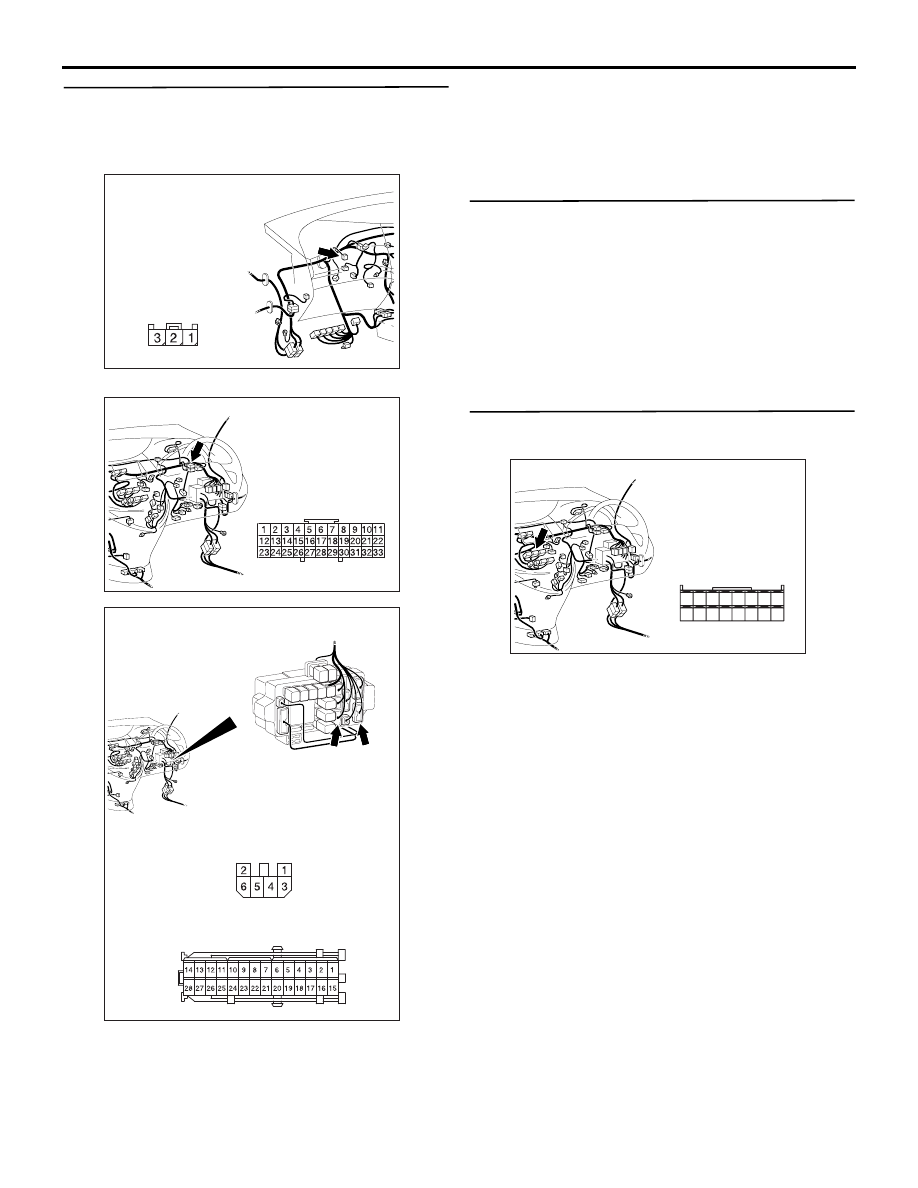
Connector: C-105 <RHD>
Harness side
31
32
33
34
35
36
37
38
39
40
41
42
43
44
45
46