Mitsubishi Grandis. Manual - part 291


  Index      Mitsubishi     Mitsubishi Grandis - service repair manual


Search            


Content   ..  289  290  291  292   ..


Mitsubishi Grandis. Manual - part 291


TROUBLESHOOTING

HEATER, AIR CONDITIONER AND VENTILATION

55-49

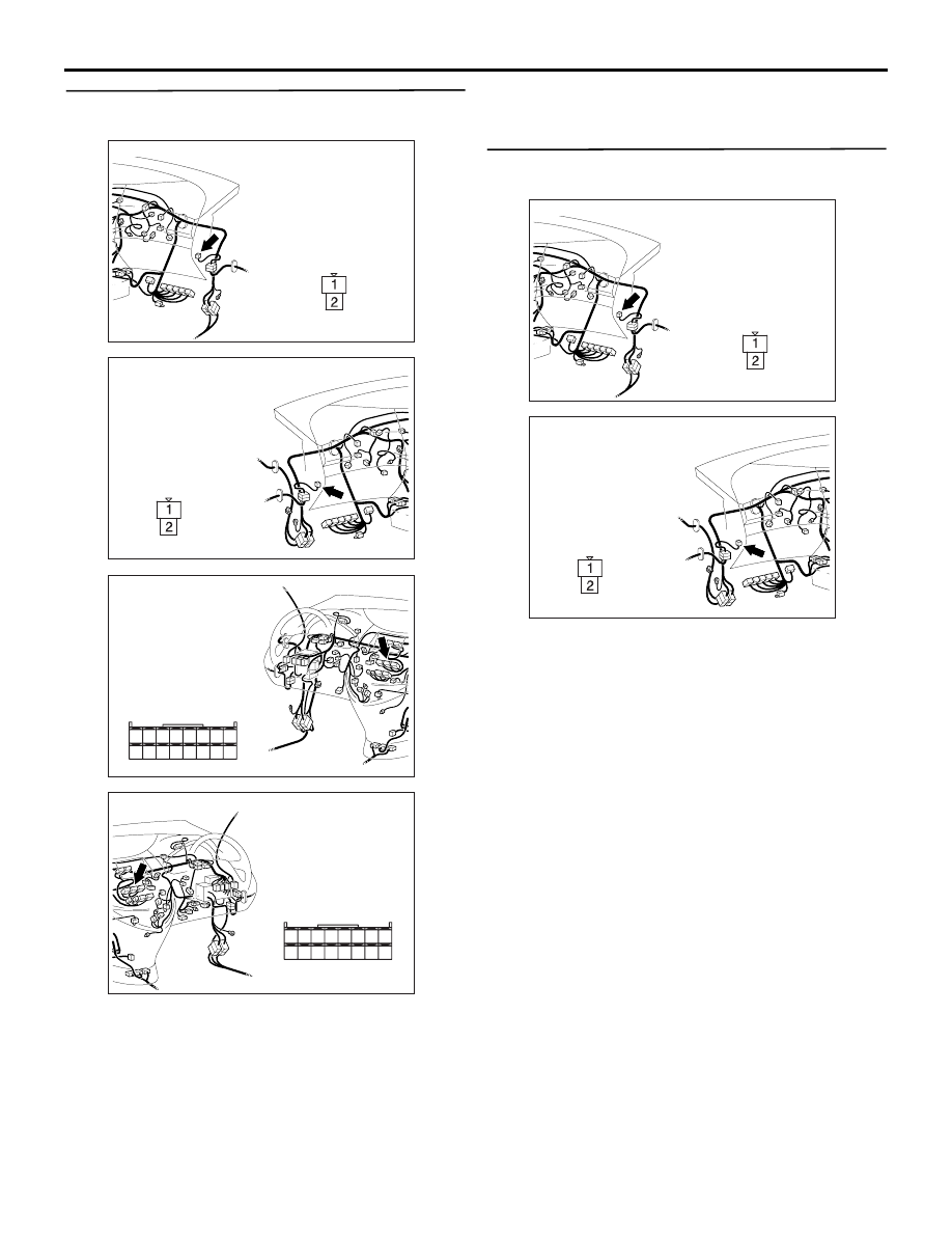
Step 6. Connector check: C-13 front blower 
motor connector and C-105 A/C-ECU connector

Q: Is the check result normal?

YES : 

Go to Step 7.

NO : 

Repair the connector.

Step 7. Voltage measurement at the C-13 front 
blower motor controller connector.

(1) Disconnect the connector, and measure at the 

wiring harness side.

AC310615

AF

Connector: C-13 <LHD>

Harness side

AC310628AF

Connector: C-13 <RHD>

Harness side

AC310613

AC

Connector: C-105 <LHD>

Harness side

31

32

33

34

35

36

37

38

39

40

41

42

43

44

45

46

AC310631AC

Connector: C-105 <RHD>

Harness side

31

32

33

34

35

36

37

38

39

40

41

42

43

44

45

46

AC310615

AF

Connector: C-13 <LHD>

Harness side

AC310628AF

Connector: C-13 <RHD>

Harness side

TROUBLESHOOTING

HEATER, AIR CONDITIONER AND VENTILATION

55-50

(2) Turn the ignition switch to the ON position.

(3) Disconnect A/C-ECU connector C-105, and earth 

terminal 45.

(4) measure the voltage between terminal 1 and 

body earth.

OK: System voltage

Q: Is the check result normal?

YES : 

Go to Step 14.

NO : 

Go to Step 8.

Step 8. Voltage measurement at C-209 front 
blower relay connector.

(1) Remove the relay, and measure at the junction 

block side.

(2) Turn the ignition switch to the ON position.

(3) Voltage between terminal 3 and body earth.

OK: System voltage

Q: Is the check result normal?

YES : 

Go to Step 10.

NO : 

Go to Step 9.

AC310613

AC

Connector: C-105 <LHD>

Harness side

31

32

33

34

35

36

37

38

39

40

41

42

43

44

45

46

AC310631AC

Connector: C-105 <RHD>

Harness side

31

32

33

34

35

36

37

38

39

40

41

42

43

44

45

46

AC309471

31

32

33

34

35

36

37

38

39

40

41

42

43

44

45

46

AC309471

Connector C-105
(Harness side)

AD

AC310507

Connector C-13 
(Harness side)

AO

AC310623

Connector: C-209 <LHD>

AD

3

4

5

1

2

Junction block side

Junction block (Front view)

AC310618

Connector: C-209 <RHD>

AD

3

4

5

1

2

Junction block side

Junction block (Front view)

AC310507AP

Connector C-209 
(Junction block side)

3

4

5

1

2

TROUBLESHOOTING

HEATER, AIR CONDITIONER AND VENTILATION

55-51

Step 9. Check the wiring harness between C-209 
front blower relay connector terminal No.3 and 
the ignition switch (IG2).

NOTE: Prior to the wiring harness inspection, check 
junction block connector C-202, and repair if 
necessary.

• Check the blower relay power supply line for 

open circuit.

Q: Is the check result normal?

YES : 

The trouble can be an intermittent 

malfunction (Refer to GROUP 00, How to 
Cope with Intermittent Malfunction 

P.00-5

.)

NO : 

Repair the wiring harness.

Step 10. Voltage measurement at C-209 front 
blower relay connector.

(1) Remove the relay, and measure at the junction 

block side.

(2) Turn the ignition switch to the ON position.

(3) Voltage between terminal 5 and body earth.

OK: System voltage

Q: Is the check result normal?

YES : 

Go to Step 12.

NO : 

Go to Step 11.

AC310624

Connectors: C-202, C-209 <LHD>

AC

3

4

5

1

2

Junction block side

Junction block (Front view)

C-209

C-202

C-209

Harness side

C-202

AC310619

Connectors: C-202, C-209 <RHD>

AC

3

4

5

1

2

Junction block side

Junction block (Front view)

C-209

C-202

C-209

Harness side

C-202

AC310623

Connector: C-209 <LHD>

AD

3

4

5

1

2

Junction block side

Junction block (Front view)

AC310618

Connector: C-209 <RHD>

AD

3

4

5

1

2

Junction block side

Junction block (Front view)

AC310507AQ

Connector C-209 
(Junction block side)

3

4

5

1

2

TROUBLESHOOTING

HEATER, AIR CONDITIONER AND VENTILATION

55-52

Step 11. Check the wiring harness between C-209 
front blower relay connector terminal No.5 and 
fusible link (30).

NOTE: 

Prior to the wiring harness inspection, check 
intermediate connectors C-125 and junction block 
connector C-204, and repair if necessary.

• Check the blower relay power supply line for 

open circuit.

Q: Is the check result normal?

YES : 

The trouble can be an intermittent 

malfunction (Refer to GROUP 00, How to 
Cope with Intermittent Malfunction 

P.00-5

.)

NO : 

Repair the wiring harness.

AC310624

Connectors: C-204, C-209 <LHD>

AD

3

4

5

1

2

Junction block side

Junction block (Front view)

C-209

C-204 (B)

C-209

Harness side

C-204

AC310619

Connectors: C-204, C-209 <RHD>

AD

3

4

5

1

2

Junction block side

Junction block (Front view)

C-209

C-204 (B)

C-209

Harness side

C-204

AC310613

AD

Connector: C-125 <LHD>

AC310628AB

Connector: C-125 <RHD>


Content   ..  289  290  291  292   ..