Mitsubishi Grandis. Manual - part 281
TROUBLESHOOTING
HEATER, AIR CONDITIONER AND VENTILATION
55-9
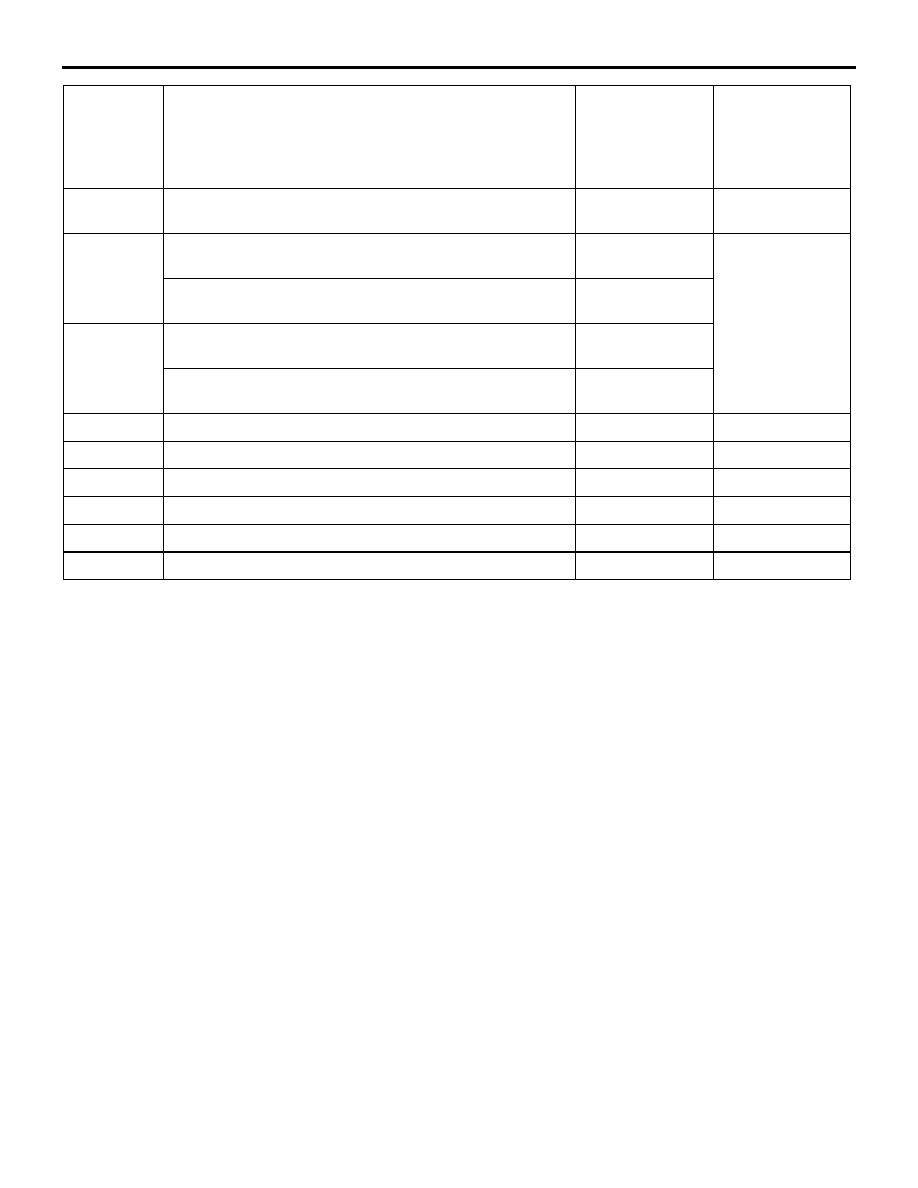
B1055
Motor drive system for rear air mix damper <vehicles
with dual automatic A/C>
−
B1061
Potentiometer system for air outlet switching damper
(short to power supply) <LHD>
Moved to DEF
position
Potentiometer system for air outlet switching damper
(short to power supply) <RHD>
B1062
Potentiometer system for air outlet switching damper
(short to earth or open circuit) <LHD>
Potentiometer system for air outlet switching damper
(short to earth or open circuit) <RHD>
B1065
Motor drive system for air outlet switching damper
−
U1073
Bus off error
−
U1100
Engine-related CAN time-out
−
U1109
ETACS related CAN communication time-out
−
U1113
Multi-centre display-related CAN time-out
−
U1120
Engine-related failure data
−
Code No.
Diagnostic item
Reference page Service data
display
contents when
diagnosis code
is set