Mitsubishi Grandis. Manual - part 254
INPUT SIGNAL PROCEDURES
SMART WIRING SYSTEM (SWS) USING SWS MONITOR
54C-478
YES :
The trouble can be an intermittent
malfunction (Refer to GROUP 00
− How to
Cope with Intermittent Malfunction
NO :
Replace the ETACS-ECU.
Inspection Procedure Q-6: The column switch (lighting, turn-signal lamp and headlamp washer
switch) signal is not received.
CAUTION
Whenever the ECU is replaced, ensure that the
input signal circuit is normal.
COMMENTS ON TROUBLE SYMPTOM
Input signal from the column switch (lighting,
turn-signal lamp and headlamp washer switch) is
used to operate the functions below. If the signal is
abnormal, these functions will not work normally.
• Lamp reminder function
• Headlamp washer
• Headlamp and tail lamp
• Headlamp automatic-shutdown function
• Front and rear fog lamp
• Turn signal lamp
• Headlamp washer
POSSIBLE CAUSES
• Malfunction of the column switch
• Damaged harness wires and connectors
DIAGNOSIS PROCEDURE
Step 1. Check the column switch connector.
Check that the wiper and washer switch connector,
the lighting switch connector and the switch body
connector are in good condition.
Q: Is the check result normal?
YES :
Go to Step 2.
NO :
Repair the defective connector.
Step 2. Check the column switch (lighting switch
and switch body).
Refer to GROUP 54A
− Column switch
Q: Is the check result normal?
YES :
Go to Step 3.
NO :
Replace the column switch.
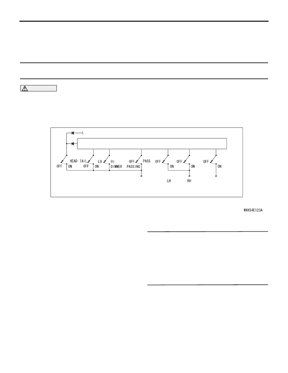
COLUMN-ECU
DIMMER·
PASSING SWITCH
TURN-SIGNAL
LAMP SWITCH
LIGHTING
SWITCH
HEADLAMP
WASHER SWITCH
COLUMN SWITCH
Lighting Switch Input Circuit