Mitsubishi Grandis. Manual - part 231


  Index      Mitsubishi     Mitsubishi Grandis - service repair manual


Search            


Content   ..  229  230  231  232   ..


Mitsubishi Grandis. Manual - part 231


SYMPTOM PROCEDURES

SMART WIRING SYSTEM (SWS) USING SWS MONITOR

54C-386

Normal conditions are displayed for all the items. : 

Go to Step 3.

Normal condition is not displayed for item No.03 : 

Refer to inspection procedure Q-11 "The 
key reminder switch signal is not received 

P.54C-493

."

Normal condition is not displayed for item No.05, 
07, 41 or 42 : 

Refer to inspection procedure Q-14 

"All the door switch signals are not received 

P.54C-505

."

Normal condition is not displayed for item No.21 
and 22 : 

Refer to inspection procedure Q-15 "The 

driver's door lock actuator switch signal is 
not received <LH drive vehicles>

P.54C-514


or <RH drive vehicles>

P.54C-518

 ."

Normal condition is not displayed for item No.31 or 
32 : 

Refer to inspection procedure Q-22 "The 
interior lamp "all on" or "all off" switch signal 
is not sent to the ETACS-ECU 

P.54C-553

."

Step 3. Retest the system.

Check that the right or left room lamp illuminates 
when the interior lamp switch is operated.

Q: Is the check result normal?

YES : 

Go to Step 6.

NO : 

Go to Step 4.

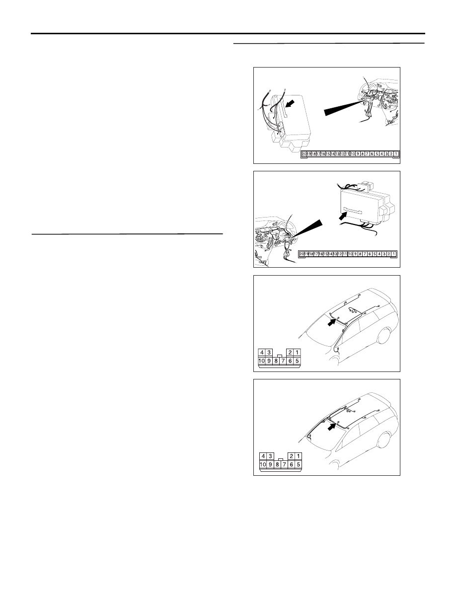
Step 4. Connector check: C-219 ETACS-ECU 
connector, E-02 room lamp connector

Q: Is the check result normal?

YES : 

Go to Step 5.

NO : 

Repair the defective connector.

AC310626

Connector: C-219

Junction block (Rear view)

<LHD>

AB

Junction block side

AC310620

Connector: C-219

Junction block 
(Rear view)

<RHD>

AB

Junction block side

AC310651

AD

Connector: E-02 <LHD>             

Harness side

AC310655

AE

Connector: E-02 <RHD>             

Harness side

SYMPTOM PROCEDURES

SMART WIRING SYSTEM (SWS) USING SWS MONITOR

54C-387

Step 5. Check the wiring harness from C-219 
ETACS-ECU connector terminal No.6 to E-02 
room lamp connector terminal No.10.

NOTE: 

Prior to the wiring harness inspection, check 
intermediate connector E-11 and junction block 
connector C-211, and repair if necessary.

• Check the power supply line for open circuit.

Q: Is the check result normal?

YES : 

Replace the room lamp.

NO : 

Repair the wiring harness.

Step 6. Check the room lamp switch.

Check which position (ON or DOOR) of the room 
lamp switch does not activate the room lamp.

Q: Which switch position does not activate the lamp?

The lamp illuminates at neither the ON nor DOOR 
position.  : 

Go to Step 7.

The lamp does not illuminate at the ON position. : 

Go to Step 7.

The lamp does not illuminate at the DOOR position. 

Go to Step 9.

AC310626

Connector: C-219

Junction block (Rear view)

<LHD>

AB

Junction block side

AC310620

Connector: C-219

Junction block 
(Rear view)

<RHD>

AB

Junction block side

AC310651

AD

Connector: E-02 <LHD>             

Harness side

AC310655

AE

Connector: E-02 <RHD>             

Harness side

AC310623

AC310623

Connector: C-211

AQ

<LHD>

Junction block (Front view)

Harness side

3

1

2

AC310618

AC310618

Connector: C-211 <RHD>

AS

Harness side

Junction block (Front view)

3

1

2

SYMPTOM PROCEDURES

SMART WIRING SYSTEM (SWS) USING SWS MONITOR

54C-388

Step 7. Connector check: E-02 room lamp 
connector

Q: Is the check result normal?

YES : 

Go to Step 8.

NO : 

Repair the defective connector.

Step 8. Check the bulbs of the room lamp.

Check that the room lamp bulbs are not burned out.

Q: Is the check result normal?

YES : 

Replace the room lamp.

NO : 

Replace the room lamp bulb.

Step 9. Connector check: E-02 room lamp 
connector

Q: Is the check result normal?

YES : 

Go to Step 10.

NO : 

Repair the defective connector.

Step 10. Check the bulbs of the room lamp.

Check that the room lamp bulbs are not burned out.

Q: Is the check result normal?

YES : 

Go to Step 11.

NO : 

Replace the room lamp bulb.

AC310651

AD

Connector: E-02 <LHD>             

Harness side

AC310655

AE

Connector: E-02 <RHD>             

Harness side

AC310651

AD

Connector: E-02 <LHD>             

Harness side

AC310655

AE

Connector: E-02 <RHD>             

Harness side

SYMPTOM PROCEDURES

SMART WIRING SYSTEM (SWS) USING SWS MONITOR

54C-389

Step 11. Connector check: C-219 ETACS-ECU 
connector

Q: Is the check result normal?

YES : 

Go to Step 12.

NO : 

Repair the defective connector.

AC310626

Connector: C-219

Junction block (Rear view)

<LHD>

AB

Junction block side

AC310620

Connector: C-219

Junction block 
(Rear view)

<RHD>

AB

Junction block side


Content   ..  229  230  231  232   ..