Mitsubishi Grandis. Manual - part 196


  Index      Mitsubishi     Mitsubishi Grandis - service repair manual


Search            


Content   ..  194  195  196  197   ..


Mitsubishi Grandis. Manual - part 196


SYMPTOM PROCEDURES

SMART WIRING SYSTEM (SWS) USING SWS MONITOR

54C-246

"OK" is displayed for all the items : 

Go to Step 2.

"NG" is displayed on the "COLUMN ECU" menu. : 

Refer to Inspection Procedure A-2 
"Communication with the column switch 
(column-ECU) is not possibl

P.54C-56

."

"NG" is displayed on the "FRONT ECU" menu. : 

Refer to Inspection Procedure A-4 
"Communication with the front-ECU is not 
possibl

P.54C-70

."

Step 2. SWS monitor data list.

Check the SWS communication signal, which are 
related to the headlamp washer function.

<Selected item> HD WASHER

• Turn the ignition switch to the ACC position.

• Headlamp washer switch: ON

OK: Normal conditions are displayed for all 
the items.

Q: Are the check result normal?

Normal conditions are displayed for all the items : 

Go to Step 3.

Normal condition is not displayed for item No.16 : 

Replace the column switch.

Normal condition is not displayed for item No.31 : 

Refer to inspection procedure Q-1 "The 
ignition switch (ACC) signal is not received 

P.54C-456

."

Normal condition is not displayed for item No.70 : 

Replace the front-ECU.

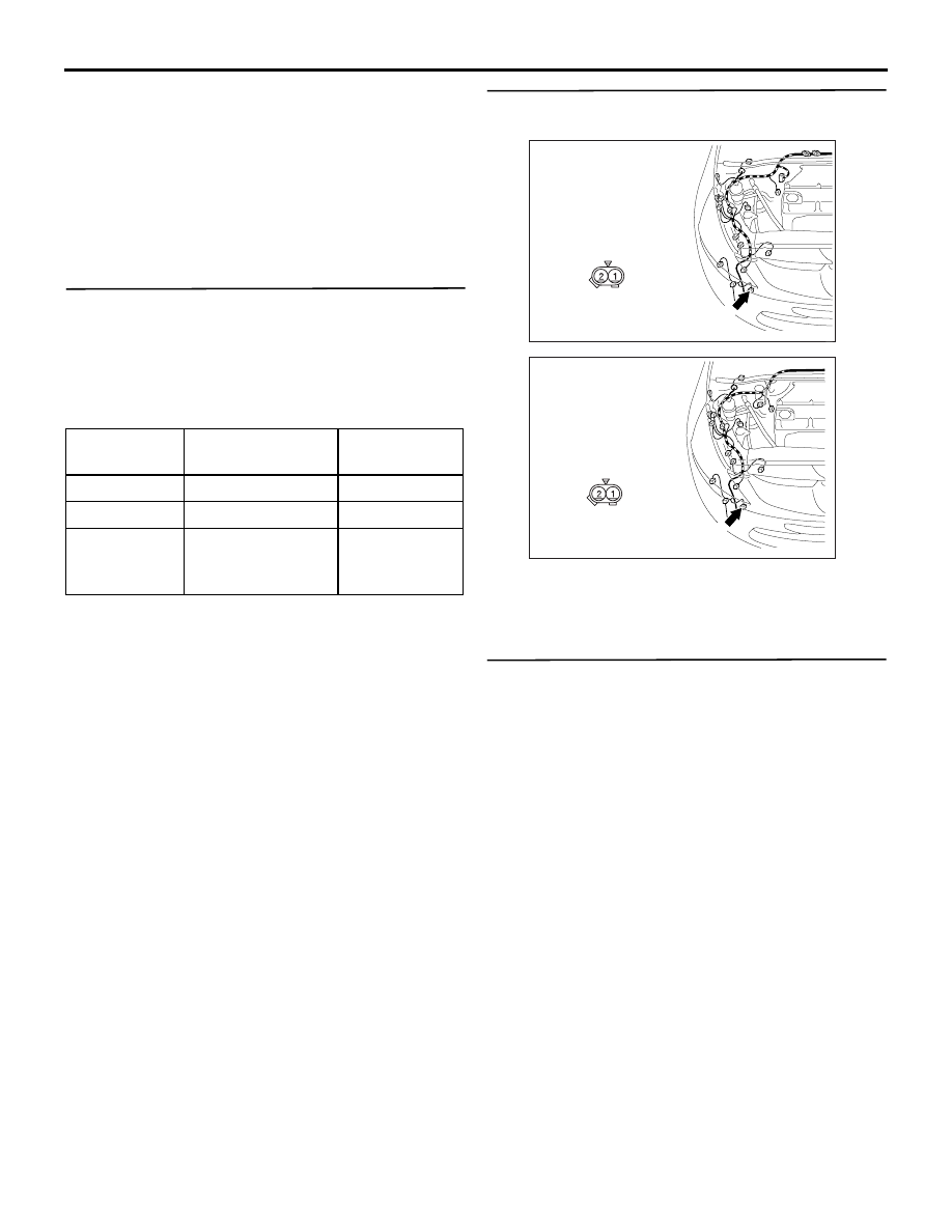
Step 3. Connector check: A-31 headlamp washer 
motor connector.

Q: Is the check result normal?

YES : 

Go to Step 4.

NO : 

Repair the connector.

Step 4. Check the headlamp washer motor 
assembly.

Refer to GROUP 51 

− Headlamp washer 

P.51-35

.

Q: Is the check result normal?

YES : 

Go to Step 5.

NO : 

Replace the headlamp washer motor.

Item No.

Item name

Normal 
condition

Item 16

HD WASHER SW ON

Item 31

IG SW (ACC)

ON

Item 70

FRONT ECU ACK NORMAL ACK 

or HI-BEAM 
ACK

AC310401

Connector : A-31 <LHD>

AH

A-31(GR)

Harness side

AC310396

Connector : A-31 <RHD>

AH

A-31(GR)

Harness side

SYMPTOM PROCEDURES

SMART WIRING SYSTEM (SWS) USING SWS MONITOR

54C-247

Step 5. Resistance measurement at the A-31 
headlamp washer motor connector.

(1) Disconnect the connector, and measure at the 

wiring harness side.

(2) Continuity between A-31 headlamp washer motor 

connector terminal No.2 and body earth.

OK: 2 

 or less

Q: Is the check result normal?

YES : 

Go to Step 8.

NO : 

Go to Step 6.

Step 6. Connector check: A-40 earth connector.

Q: Is the check result normal?

YES : 

Go to Step 7.

NO : 

Repair the connector.

AC310401

Connector : A-31 <LHD>

AH

A-31(GR)

Harness side

AC310396

Connector : A-31 <RHD>

AH

A-31(GR)

Harness side

AC310506

AC310506

Connector A-31
(Harness side)

BP

AC310401

Connector: A-40 <LHD>

Harness side

AE

A-40 (GR)

AC310396

Connector: A-40 <RHD>

Harness side

AE

A-40 (GR)

SYMPTOM PROCEDURES

SMART WIRING SYSTEM (SWS) USING SWS MONITOR

54C-248

Step 7. Check the wiring harness between A-31 
headlamp washer motor connector terminal No.2 
and A-40 earth connector terminal No.2.

• Check the earth wires for open circuit.

Q: Is the check result normal?

YES : 

The trouble can be an intermittent 

malfunction (Refer to GROUP 00 

− How to 

Cope with Intermittent Malfunction 

P.00-5

).

NO : 

Repair the wiring harness.

Step 8. Connector check: A-14X front-ECU 
connector.

Q: Is the check result normal?

YES : 

Go to Step 9.

NO : 

Repair the connector.

Step 9. Voltage measurement at the A-14X 
front-ECU connector.

(1) Remove the front-ECU, and measure at the 

junction block side.

(2) Ignition switch: ACC

(3) Check the voltage between the A-14X front-ECU 

connector terminal No.9 and body earth.

OK: System voltage

Q: Is the check result normal?

YES : 

Go to Step 11.

NO : 

Go to Step 10.

AC310401

Connector : A-31 <LHD>

AH

A-31(GR)

Harness side

AC310396

Connector : A-31 <RHD>

AH

A-31(GR)

Harness side

AC310401

Connector: A-40 <LHD>

Harness side

AE

A-40 (GR)

AC310396

Connector: A-40 <RHD>

Harness side

AE

A-40 (GR)

AC311521AB

Connector: A-14X

Relay box side

AC311521AB

Connector: A-14X

Relay box side

AC310507CB

Connector A-14X 
(Harness side)

SYMPTOM PROCEDURES

SMART WIRING SYSTEM (SWS) USING SWS MONITOR

54C-249

Step 10. Check the wiring harness between 
A-14X front-ECU connector terminal No.9 and the 
fusible link (5).

• Check the power supply line for open circuit.

Q: Is the check result normal?

YES : 

The trouble can be an intermittent 

malfunction (Refer to GROUP 00 

− How to 

Cope with Intermittent Malfunction 

P.00-5

).

NO : 

Repair the wiring harness.

Step 11. Check the wiring harness between A-31 
headlamp washer motor connector terminal No.1 
and A-14X front-ECU connector terminal No.11.

• Check the output line for open circuit.

Q: Is the check result normal?

YES : 

Go to Step 12.

NO : 

Repair the wiring harness.

Step 12. Retest the system.

The headlamp washer should now work normally.

Q: Is the check result normal?

YES : 

The trouble can be an intermittent 

malfunction (Refer to GROUP 00 

− How to 

Cope with Intermittent Malfunction 

P.00-5

).

NO : 

Replace the front-ECU.

AC311521AB

Connector: A-14X

Relay box side

AC311521AB

Connector: A-14X

Relay box side

AC310401

Connector : A-31 <LHD>

AH

A-31(GR)

Harness side

AC310396

Connector : A-31 <RHD>

AH

A-31(GR)

Harness side


Content   ..  194  195  196  197   ..