Mitsubishi Grandis. Manual - part 185


  Index      Mitsubishi     Mitsubishi Grandis - service repair manual


Search            


Content   ..  183  184  185  186   ..


Mitsubishi Grandis. Manual - part 185


SYMPTOM PROCEDURES

SMART WIRING SYSTEM (SWS) USING SWS MONITOR

54C-202

"OK" are displayed for all the items : 

Go to Step 7.

"NG" is displayed on the "ETACS ECU" menu. : 

Refer to Inspection Procedure A-3 
"Communication with the ETACS-ECU is 
not possible 

P.54C-63

."

"NG" is displayed on the "P/W MODULE" menu. : 

Refer to Inspection Procedure A-5 
"Communication with the power window 
main switch (power window module) is not 
possibl

P.54C-77

."

"NG" is displayed on the "SUNROOF ECU" menu. : 

Refer to Inspection Procedure A-6 
"Communication with the sunroof motor 
assembly (sunroof-ECU) is not possible 

P.54C-90

."

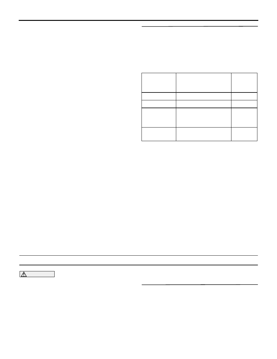
Step 7. SWS monitor data list.

Check the SWS communication signal, which are 
related to the sunroof inhibition function.

<Selected item> S/R- REAR S/R LOCK

• Ignition switch: ON

• Power window lock switch :ON

• Operate the sunroof switch

OK: Normal conditions are displayed for all 
the items.

Q: Are the check result normal?

Normal conditions are displayed for all the items : 

The trouble can be an intermittent 
malfunction (Refer to GROUP 00 

− How to 

Cope with Intermittent Malfunction 

P.00-5

).

Normal condition is not displayed for item No.30 : 

Refer to inspection procedure Q-2 "The 
ignition switch (IG1) signal is not received 

P.54C-460

."

Normal condition is not displayed for item No.43 : 

Replace the ETACS.

Normal condition is not displayed for item No.71 : 

Replace the power window main switch.

Normal condition is not displayed for item No.72 : 

Replace the sunroof motor assembly.

Inspection Procedure F-5: Sunroof anti-trap function does not work normally.

CAUTION

Whenever the ECU is replaced, ensure that the 
input and output signal circuits are normal.

COMMENTS ON TROUBLE SYMPTOM

If the sunroof anti-trap function does not work, the 
sunroof motor assembly (sunroof-ECU) may be 
defective.

POSSIBLE CAUSES

• Malfunction of the sunroof motor assembly 

(sunroof-ECU)

DIAGNOSTIC PROCEDURE

Retest the system.

Check that the sunroof anti-trap function work 
normally.

Q: Is the check result normal?

YES : 

The trouble can be an intermittent 

malfunction (Refer to GROUP 00 

− How to 

Cope with Intermittent Malfunction 

P.00-5

).

NO : 

Replace the sunroof motor assembly.

Item No.

Item name

Normal 
condition
s

Item 30

IG SW(IG1)

ON

Item 43

BUZZER

ON

Item 71

P/W ECU ACK

P/W 
LOCK 
ACK

Item 72

S/R ECU ACK

BUZZER 
ACK

SYMPTOM PROCEDURES

SMART WIRING SYSTEM (SWS) USING SWS MONITOR

54C-203

WINDSHIELD WIPER AND WASHER

Inspection Procedure G-1: The windshield wipers does not work at all.

CAUTION

Whenever the ECU is replaced, ensure that the 
input and output signal circuits are normal.

Windshield Wiper Power Supply Circuit

FRONT-ECU

WINDSHIELD 
WIPER MOTOR

WIPER SPEED 
SWITCHING 
RELAY

CIRCUIT
BREAKER

IGNITION 
SWITCH (ACC)

Wire colour code
B : Black     LG : Light green     G : Green     L : Blue     W : White     Y : Yellow     SB : Sky blue
BR : Brown     O : Orange     GR : Gray     R : Red     P : Pink     V : Violet   

SYMPTOM PROCEDURES

SMART WIRING SYSTEM (SWS) USING SWS MONITOR

54C-204

COMMENTS ON TROUBLE SYMPTOM

The windshield wiper motor, the column switch or the 
front-ECU may be defective. If a problem is found in 
the ECU check by using the SWS monitor, also 
check the wiper backup circuit (between C-301 
column switch connector terminal No.8 and A-15X 
front-ECU connector terminal No.26) and repair if 
necessary.

POSSIBLE CAUSES

• Malfunction of the windshield wiper motor

• Malfunction of the column switch

• Malfunction of the front-ECU

• Damaged harness wires and connectors

DIAGNOSIS PROCEDURE

Step 1. ECU check by using the SWS monitor.

Check that the power supply and earth lines to the 
column switch (column-ECU) and the front-ECU and 
the SWS communication lines are normal.

• Turn the ignition switch to the ON position.

ECUS TO BE CHECKED

• COLUMN ECU

• FRONT-ECU

OK: "OK" are displayed for all the items

Q: Are the check result normal?

"OK" is displayed for all the items : 

Go to Step 2.

"NG" is displayed on the "COLUMN ECU" menu. : 

Refer to Inspection Procedure A-2 
"Communication with the column switch 
(column-ECU) is not possibl

P.54C-56

."

"NG" is displayed on the "FRONT ECU" menu. : 

Refer to Inspection Procedure A-4 
"Communication with the front-ECU is not 
possibl

P.54C-70

."

Step 2. Function diagnosis by using the SWS 
monitor.

Check the SWS communication signal, which are 
related to the windshield wiper function.

<Selected item> F.WIPER INT

• Turn the ignition switch to the ACC position.

• Windshield wiper switch: INT

OK: Normal conditions are displayed for all 
the items.

Q: Are the check result normal?

Normal conditions displayed for all the items : 

Go 

to Step 3.

Normal condition is not displayed for item No.05 : 

Replace the column switch.

Normal condition is not displayed for item No.31 : 

Refer to inspection procedure Q-1 "The 
ignition switch (ACC) signal is not received 

P.54C-456

."

Normal condition is not displayed for item No.70 : 

Replace the front-ECU.

Item No. Item name

Normal condition

Item 05

INT WIPER SW

ON

Item 31

IGNITION SW 
ACC

ON

Item 70

FRONT ECU ACK NORMAL ACK or 

HI-BEAM ACK

SYMPTOM PROCEDURES

SMART WIRING SYSTEM (SWS) USING SWS MONITOR

54C-205

Step 3. Connector check: A-01 windshield wiper 
motor connector.

Q: Is the check result normal?

YES : 

Go to Step 4.

NO : 

Repair the connector.

Step 4. Check the windshield wiper motor 
assembly.

Refer to GROUP 51 

− Windshield wiper 

P.51-25

.

Q: Is the check result normal?

YES : 

Go to Step 5

NO : 

Replace the windshield wiper motor 
assembly.

Step 5. Resistance measurement at the A-01 
windshield wiper motor connector.

(1) Disconnect the connector, and measure at the 

wiring harness side.

(2) Continuity between A-01 windshield wiper motor 

connector terminal No.2, and body earth

OK: 2 

 or less

Q: Is the check result normal?

YES : 

Go to Step 8.

NO : 

Go to Step 6.

AC310401

Connector: A-01 <LHD>

Harness side

AD

A-01 (GR)

AC310396

Connector: A-01 <RHD>

Harness side

AD

A-01 (GR)

AC310401

Connector: A-01 <LHD>

Harness side

AD

A-01 (GR)

AC310396

Connector: A-01 <RHD>

Harness side

AD

A-01 (GR)

AC310506

4

1

2

5

3

Connector A-01 
(Harness side)

BN


Content   ..  183  184  185  186   ..