Mitsubishi Grandis. Manual - part 158


  Index      Mitsubishi     Mitsubishi Grandis - service repair manual


Search            


Content   ..  156  157  158  159   ..


Mitsubishi Grandis. Manual - part 158


SYMPTOM PROCEDURES

SMART WIRING SYSTEM (SWS) USING SWS MONITOR

54C-94

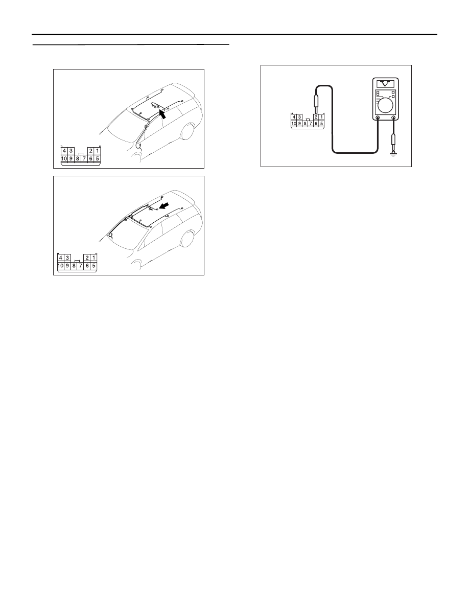
Step 5. Voltage measurement at E-07 sunroof 
motor assembly connector.

(1) Disconnect the connector, and measure at the 

wiring harness side.

(2) Turn the ignition switch to the ON position.

(3) Voltage between E-07 sunroof motor assembly 

connector terminal No.2 and body earth

OK: System voltage

Q: Is the check result normal?

YES : 

Go to Step 7.

NO : 

Go to Step 6.

AC310651

AB

Connector: E-07 <LHD>             

Harness side

AC310655

AC

Connector: E-07 <RHD>             

Harness side

AC310507 CH

Connector E-07 
(harness side)

SYMPTOM PROCEDURES

SMART WIRING SYSTEM (SWS) USING SWS MONITOR

54C-95

Step 6. Check the wiring harness between E-07 
sunroof motor assembly connector terminal No.2 
and ignition switch (IG2).

NOTE: 

Prior to the wiring harness inspection, check junction 
block connectors C-202 and C-211, and repair if 
necessary.

• Check the power supply line to the ignition switch 

(IG2) for open circuit.

Q: Is the check result normal?

YES : 

The trouble can be an intermittent 

malfunction (Refer to GROUP 00, How to 
Cope with Intermittent Malfunction 

P.00-5

).

NO : 

Repair the wiring harness.

AC310651

AB

Connector: E-07 <LHD>             

Harness side

AC310655

AC

Connector: E-07 <RHD>             

Harness side

AC310624

Connectors: C-202, C-211

AV

<LHD>

Junction block (Front view)

C-211

C-202

C-202

C-211

Harness side

Harness side

4

6 5

3

2

1

3

1

2

AC310619

Connectors: C-202, C-211

AV

<RHD>

Junction block (Front view)

C-211

C-202

C-202

C-211

Harness side

Harness side

4

6 5

3

2

1

3

1

2

SYMPTOM PROCEDURES

SMART WIRING SYSTEM (SWS) USING SWS MONITOR

54C-96

Step 7. Resistance measurement at E-07 sunroof 
motor assembly connector.

(1) Disconnect the connector, and measure at the 

wiring harness side.

(2) Continuity between E-07 sunroof motor assembly 

connector terminal No.5 and body earth

OK: 2 

 or less

Q: Is the check result normal?

YES : 

Go to Step 9.

NO : 

Go to Step 8.

Step 8. Check the wiring harness between E-07 
sunroof motor assembly connector terminal No.5 
and body earth.

• Check the earth wires for open circuit.

Q: Is the check result normal?

YES : 

The trouble can be an intermittent 

malfunction (Refer to GROUP 00, How to 
Cope with Intermittent Malfunction 

P.00-5

).

NO : 

Repair the wiring harness.

AC310651

AB

Connector: E-07 <LHD>             

Harness side

AC310655

AC

Connector: E-07 <RHD>             

Harness side

AC310506

Connector E-07 
(Harness side)

BH

AC310651

AB

Connector: E-07 <LHD>             

Harness side

AC310655

AC

Connector: E-07 <RHD>             

Harness side

SYMPTOM PROCEDURES

SMART WIRING SYSTEM (SWS) USING SWS MONITOR

54C-97

Step 9. Connector check: C-221 ETACS-ECU 
connector

Q: Is the check result normal?

YES : 

Go to Step 10.

NO : 

Repair the defective connector.

AC310626

Connector: C-221

Junction block (Rear view)

<LHD>

AC

51

52

53

54

55

56

57

58

59

60

61

62

63

64

65

66

67

68

69

70

71

72

73

74

Harness side

C-221(GR)

AC310620

Connector: C-221

Junction block 
(Rear view)

<RHD>

AC

51

52

53

54

55

56

57

58

59

60

61

62

63

64

65

66

67

68

69

70

71

72

73

74

Harness side

C-221(GR)


Content   ..  156  157  158  159   ..