Mitsubishi Grandis. Manual - part 154


  Index      Mitsubishi     Mitsubishi Grandis - service repair manual


Search            


Content   ..  152  153  154  155   ..


Mitsubishi Grandis. Manual - part 154


SYMPTOM PROCEDURES

SMART WIRING SYSTEM (SWS) USING SWS MONITOR

54C-78

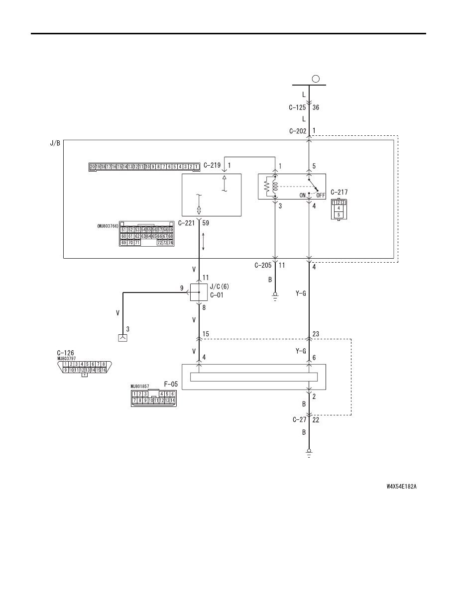
Power Window Main Switch and SWS Communication Circuit <LHD>

POWER
WINDOW RELAY

ETACS-ECU

DIAGNOSIS
CONNECTOR

POWER WINDOW
MAIN SWITCH

FUSIBLE
LINK

5

CPU

J/B SIDE

Wire colour code
B : Black     LG : Light green     G : Green     L : Blue
W : White     Y : Yellow     SB : Sky blue     BR : Brown
O : Orange     GR : Gray     R : Red     P : Pink     V : Violet

FRONT 
SIDE

SYMPTOM PROCEDURES

SMART WIRING SYSTEM (SWS) USING SWS MONITOR

54C-79

COMMENTS ON TROUBLE SYMPTOM

The power window main switch, the power supply 
circuit (power window relay driving circuit) or 
communication circuit for that switch may be 
defective.

POSSIBLE CAUSES

• Malfunction of the power window main switch

• Malfunction of the power window relay

• Malfunction of the ETACS-ECU

• Damaged harness wires and connectors

Power Window Main Switch and SWS Communication Circuit <RHD>

POWER
WINDOW RELAY

ETACS-ECU

DIAGNOSIS
CONNECTOR

POWER WINDOW
MAIN SWITCH

FUSIBLE
LINK

5

CPU

Wire colour code
B : Black     LG : Light green     G : Green     L : Blue
W : White     Y : Yellow     SB : Sky blue     BR : Brown
O : Orange     GR : Gray     R : Red     P : Pink     V : Violet

FRONT 
SIDE

SYMPTOM PROCEDURES

SMART WIRING SYSTEM (SWS) USING SWS MONITOR

54C-80

DIAGNOSIS PROCEDURE

Step 1. ECU check by using the SWS monitor

Check that the power supply and earth lines to the 
ETACS-ECU and the SWS communication lines are 
normal.

• Ignition switch: OFF

ECUS TO BE CHECKED

• ETACS ECU

OK: "OK" is displayed on the "ETACS ECU" 
menu.

Q: Is the check result normal?

YES : 

Go to Step 2.

NO : 

Refer to Inspection Procedure A-3 
"Communication with the ETACS-ECU is 
not possible 

P.54C-63

."

Step 2. SWS monitor data list
<Selected item> ETACS ECU

• Ignition switch: ON

OK: Normal condition is displayed.

Q: Is the check result normal?

YES : 

Go to Step 3.

NO : 

Refer to inspection procedure Q-2 "The 
ignition switch (IG1) signal is not received 

P.54C-460

."

Step 3. Connector check: F-05 power window 
main switch connector.

Q: Is the check result normal?

YES : 

Go to Step 4.

NO : 

Repair the defective connector.

Step 4. Voltage measurement at the F-05 power 
window main switch connector.

(1) Disconnect the connector, and measure at the 

wiring harness side.

Item No.

Item name

Normal 
condition

Item 30

IG SW(IG1)

ON

AC311150

AB

Connector: F-05

Harness side

<LHD>

10

1

6

14

5

12

13

4

11

7

2

3

8

9

F-05(B)

AC310213

Connector: F-05

Harness side

<RHD>

10

1

6

14

5

12

13

4

11

7

2

3

8

9

F-05(B)

AB

AC311150

AB

Connector: F-05

Harness side

<LHD>

10

1

6

14

5

12

13

4

11

7

2

3

8

9

F-05(B)

AC310213

Connector: F-05

Harness side

<RHD>

10

1

6

14

5

12

13

4

11

7

2

3

8

9

F-05(B)

AB

SYMPTOM PROCEDURES

SMART WIRING SYSTEM (SWS) USING SWS MONITOR

54C-81

(2) Ignition switch: ON

(3) Voltage between F-05 power window main switch 

connector terminal No.6 and body earth.

OK: System voltage

Q: Is the check result normal?

YES : 

Go to Step 13.

NO : 

Go to Step 5.

Step 5. Connector check: C-217 power window 
relay connector.

Q: Is the check result normal?

YES : 

Go to Step 6.

NO : 

Repair the defective connector.

Step 6. Check the power window relay.

Refer to GROUP 42 

− Door 

P.42-28

.

Q: Is the check result normal?

YES : 

Go to Step 7.

NO : 

Replace the power window relay.

Step 7. Voltage measurement at C-217 power 
window relay connector.

(1) Remove the power window relay, and measure at 

the junction block side.

(2) Voltage between C-217 power window relay 

connector terminal No.5 and body earth.

OK: System voltage

Q: Is the check result normal?

YES : 

Go to Step 9.

NO : 

Go to Step 8.

AC310507BQ

Connector F-05
(Harness side)

10

1

6

14

5

12

13

4

11

7

2

3

8

9

AC310623

Connector: C-217

AB

3

4

5

1

2

Junction block side

<LHD>

Junction block (Front view)

AC310618

Connector: C-217

3

4

5

1

2

Junction block side

<RHD>

Junction block (Front view)

AB

AC310623

Connector: C-217

AB

3

4

5

1

2

Junction block side

<LHD>

Junction block (Front view)

AC310618

Connector: C-217

3

4

5

1

2

Junction block side

<RHD>

Junction block (Front view)

AB

AC310507BR

Connector C-217
(Junction block side)

3

4

5

1

2


Content   ..  152  153  154  155   ..