Mitsubishi Grandis. Manual - part 128


  Index      Mitsubishi     Mitsubishi Grandis - service repair manual


Search            


Content   ..  126  127  128  129   ..


Mitsubishi Grandis. Manual - part 128


INPUT SIGNAL PROCEDURES

SMART WIRING SYSTEM (SWS) NOT USING SWS MONITOR

54B-509

YES : 

Go to Step 8.

NO : 

Repair the defective connector.

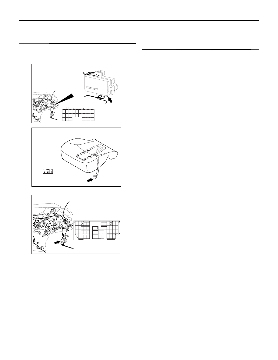
Step 8. Check the wiring harness from D-23-1 
seat occupancy sensor connector terminal No.1 
to C-220 ETACS-ECU connector terminal No.29.

NOTE: 

Prior to the wiring harness inspection, check 
intermediate connector C-16, and repair if necessary.

• Check the input line for open circuit.

Q: Is the check result normal?

YES : 

Go to Step 9.

NO : 

Repair the wiring harness or replace the 
inner seat belt (front passenger's side).

Step 9. Retest the system.
Check that the passenger’s seat belt switch signal is 
received normally.

Q: Is the check result normal?

YES : 

Intermittent malfunction (Refer to GROUP 

00 

− How to Cope with Intermittent 

Malfunction 

P.00-5

).

NO : 

Replace the ETACS-ECU.

AC310620

Connector: C-220 <RHD>

Junction block (Rear view)

AD

Harness side

21

22

23

24

25

26

27

28

29

30

31

32

33

34

35

36

37

38

39

40

41

42

43

44

AC313233

Connector: D-23-1

AC

Harness side

<RHD>

AC312043

Connector: C-16 <RHD>

AH

9

21

33

35

24

12

3 4

7

8

5 6

39

28

41

30

18

4243

31

1920

32

40

29

1617

38

27

15

37

36

26

14

13

25

2

1

34

23

11

10

22

INPUT SIGNAL PROCEDURES

SMART WIRING SYSTEM (SWS) NOT USING SWS MONITOR

54B-510

Inspection procedure Q-21: Signal is not received from the remote controlled mirror switch 
(folding/unfolding switch).

CAUTION

Whenever the ECU is replaced, ensure that the 
input signal circuit is normal.

COMMENTS ON TROUBLE SYMPTOM

The electric-folding door mirrors work in accordance 
with the input signal from the remote controlled 
mirror switch. If the input signal is abnormal, the door 
mirrors will not work normally.

POSSIBLE CAUSES

• Malfunction of the remote controlled mirror switch

• Malfunction of the ETACS-ECU

• Damaged harness wires and connectors

ETACS-
ECU

REMOTE
CONTROLLED 
MIRROR SWITCH

<RHD>

<LHD>

Remote Controlled Mirror Switch Input Circuit

FOLD 
SWITCH

Wire colour code
B : Black     LG : Light green     G : Green     L : Blue     W : White     Y : Yellow     SB : Sky blue
BR : Brown     O : Orange     GR : Gray     R : Red     P : Pink     V : Violet

INPUT SIGNAL PROCEDURES

SMART WIRING SYSTEM (SWS) NOT USING SWS MONITOR

54B-511

DIAGNOSTIC PROCEDURE

Step 1. Connector check: C-129 remote 
controlled mirror switch connector

Q: Is the check result normal?

YES : 

Go to Step 2.

NO : 

Repair the connector.

Step 2. Check the remote controlled mirror 
switch.
Refer to GROUP 51 

− Door mirror 

P.51-51

.

Q: Is the check result normal?

YES : 

Go to Step 3.

NO : 

Replace the remote controlled mirror switch.

Step 3. Resistance measurement at the C-129 
remote controlled mirror switch connector.

(1) Disconnect the connector, and measure at the 

wiring harness side.

(2) Continuity between C-129 remote controlled 

mirror switch connector terminal No.1 and body 
earth

OK: 2 

 or less

Q: Is the check result normal?

YES : 

Go to Step 5.

NO : 

Go to Step 4.

AC312031

AB

Connector: C-129

Harness side

<LHD>

AC312043AB

Connector: C-129 <RHD>

Harness side

AC312031

AB

Connector: C-129

Harness side

<LHD>

AC312043AB

Connector: C-129 <RHD>

Harness side

AC312730AC

Connector C-129
(Harness side)

INPUT SIGNAL PROCEDURES

SMART WIRING SYSTEM (SWS) NOT USING SWS MONITOR

54B-512

Step 4. Check the wiring harness between C-129 
remote controlled mirror switch connector 
terminal No.1 and body earth.

NOTE: 

Prior to the wiring harness inspection, check joint 
connector C-01 <RH drive vehicles>, and repair if 
necessary.

• Check the earth wires for open circuit.

Q: Is the check result normal?

YES : 

The trouble can be an intermittent 

malfunction (Refer to GROUP 00 

− How to 

Cope with Intermittent Malfunction 

P.00-5

).

NO : 

Repair the wiring harness.

Step 5. Connector check: C-220 ETACS-ECU 
connector

Q: Is the check result normal?

YES : 

Go to Step 6.

NO : 

Repair the connector.

AC312031

AB

Connector: C-129

Harness side

<LHD>

AC312043AB

Connector: C-129 <RHD>

Harness side

AC312043AC

Connector: C-01<RHD>

AC312037

Connector: C-220

Junction block (Rear view)

AC

<LHD>

Harness side

AC312047

Connector: C-220

Junction block (Rear view)

AC

<RHD>

Harness side


Content   ..  126  127  128  129   ..