Mitsubishi Grandis. Manual - part 109


  Index      Mitsubishi     Mitsubishi Grandis - service repair manual


Search            


Content   ..  107  108  109  110   ..


Mitsubishi Grandis. Manual - part 109


INPUT SIGNAL PROCEDURES

SMART WIRING SYSTEM (SWS) NOT USING SWS MONITOR

54B-433

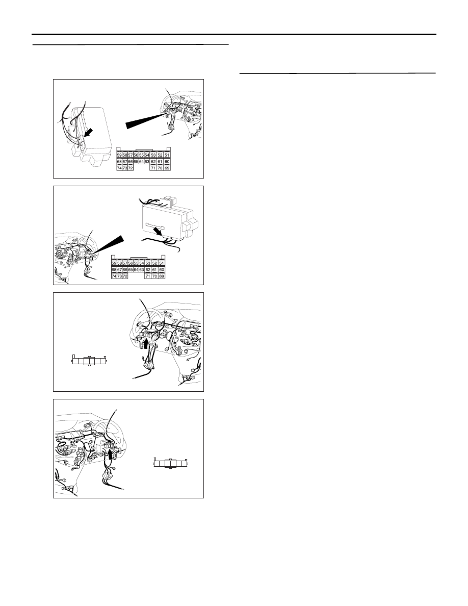
Step 6. Check the wiring harness from C-221 
ETACS-ECU connector No.54 to C-130 fog lamp 
switch connector terminal No.1.

• Check the input line for open circuit.

Q: Is the check result normal?

YES : 

Go to Step 7.

NO : 

Repair the wiring harness.

Step 7. Retest the system.
Check that the front fog lamp switch signal is 
received normally.

Q: Is the check result normal?

YES : 

The trouble can be an intermittent 

malfunction (Refer to GROUP 00 

− How to 

Cope with Intermittent Malfunction 

P.00-5

).

NO : 

Replace the ETACS-ECU.

AC312037

Connector: C-221  <LHD>

Junction block (Rear view)

AD

Harness side

AC312047

Connector: C-221  <RHD>

Junction block (Rear view)

AD

Harness side

AC312031

AF

1

5

6

4 3 2

Connector: C-130 <LHD>

Harness side

AC312043AF

1

5

6

4 3 2

Connector: C-130 <RHD>

Harness side

INPUT SIGNAL PROCEDURES

SMART WIRING SYSTEM (SWS) NOT USING SWS MONITOR

54B-434

Inspection Procedure Q-5: The driver’s door switch signal is not received. <LH drive vehicles>

CAUTION

Whenever the ECU is replaced, ensure that the 
input signal circuit is normal.

COMMENTS ON TROUBLE SYMPTOM

Input signal from the driver's door switch is used to 
operate the functions below. If the signal is abnormal, 
these functions will not work normally.

• Lamp reminder function

• Key reminder function

• Ignition key cylinder illumination lamp

• Headlamp automatic-shutdown function

• Room lamps

POSSIBLE CAUSES

• Malfunction of the driver's door switch

• Malfunction of the ETACS-ECU

• Damaged harness wires and connectors

DIAGNOSTIC PROCEDURE

Step 1. Check the installation condition.
Check that the front door switch (LH) is installed on 
the body correctly.

Q: Is the check result normal?

YES : 

Go to Step 2.

NO : 

Correct the installation condition.

Step 2. Connector check: D-17 front door switch 
(LH) connector

Q: Is the check result normal?

YES : 

Go to Step 3.

NO : 

Repair the defective connector.

Step 3. Check the front door switch (LH).
Refer to GROUP 42 

− Door 

P.42-32

.

Q: Is the check result normal?

YES : 

Go to Step 4.

NO : 

Replace the front door switch (LH).

Driver's Door Switch Input Circuit <LHD>

Wire colour code
B : Black     LG : Light green     G : Green     L : Blue     W : White     Y : Yellow     SB : Sky blue
BR : Brown     O : Orange     GR : Gray     R : Red     P : Pink     V : Violet

FRONT DOOR
SWITCH (LH)

ETACS-ECU

J/B SIDE

AC312053

Connector: D-17 <LHD>

AB

3 2 1

Harness side

INPUT SIGNAL PROCEDURES

SMART WIRING SYSTEM (SWS) NOT USING SWS MONITOR

54B-435

Step 4. Connector check: C-219 ETACS-ECU 
connector

Q: Is the check result normal?

YES : 

Go to Step 5.

NO : 

Repair the defective connector.

Step 5. Check the wiring harness between D-17 
front door switch (LH) connector terminal No.1 
and C-219 ETACS-ECU connector terminal No.10.

NOTE: 

Prior to the wiring harness inspection, check joint 
connector C-210, and repair if necessary.

• Check the input line for open circuit.

Q: Is the check result normal?

YES : 

Go to Step 6.

NO : 

Repair the wiring harness.

Step 6. Retest the system.
Check that the driver's door switch signal is received 
normally.

Q: Is the check result normal?

YES : 

The trouble can be an intermittent 

malfunction (Refer to GROUP 00 

− How to 

Cope with Intermittent Malfunction 

P.00-5

).

NO : 

Replace the ETACS-ECU.

AC312037

Connector: C-219

Junction block (Rear view)

Junction block side

AB

3

1

2

14

4

5

7 6

8

1110 9

1312

17

15

16

18

19

20

<LHD>

AC312053

Connector: D-17 <LHD>

AB

3 2 1

Harness side

AC312037

Connector: C-219

Junction block (Rear view)

Junction block side

AB

3

1

2

14

4

5

7 6

8

1110 9

1312

17

15

16

18

19

20

<LHD>

AC312035

Harness side

AC

Connector: C-210 <LHD>

7

15

5

6

1413

2

9

12

4 3

10

11

1

8

Junction block (Front view)

INPUT SIGNAL PROCEDURES

SMART WIRING SYSTEM (SWS) NOT USING SWS MONITOR

54B-436

Inspection Procedure Q-5: The driver’s door switch signal is not received. <RH drive vehicles>

CAUTION

Whenever the ECU is replaced, ensure that the 
input signal circuit is normal.

COMMENTS ON TROUBLE SYMPTOM

Input signal from the front door switch (RH) is used to 
operate the functions below. If the signal is abnormal, 
these functions will not work normally.

• Lamp reminder function

• Headlamp automatic-shutdown function

• Room lamps

POSSIBLE CAUSES

• Malfunction of the driver's door switch

• Malfunction of the ETACS-ECU

• Damaged harness wires and connectors

DIAGNOSTIC PROCEDURE

Step 1. Check the installation condition.
Check that the front door switch (RH) is installed on 
the body correctly.

Q: Is the check result normal?

YES : 

Go to Step 2.

NO : 

Correct the installation condition.

Step 2. Connector check: D-02 front door switch 
(RH) connector

Q: Is the check result normal?

YES : 

Go to Step 3.

NO : 

Repair the defective connector.

Step 3. Check the front door switch (RH).
Refer to GROUP 42 

− Door 

P.42-32

.

Q: Is the check result normal?

YES : 

Go to Step 4.

NO : 

Replace the front door switch (RH).

Driver's Door Switch Input Circuit <RHD>

Wire colour code
B : Black     LG : Light green     G : Green     L : Blue     W : White     Y : Yellow     SB : Sky blue
BR : Brown     O : Orange     GR : Gray     R : Red     P : Pink     V : Violet

FRONT DOOR
SWITCH (RH)

ETACS-ECU

J/B SIDE

AC312058

AB

Harness side

Connector: D-02 <RHD>


Content   ..  107  108  109  110   ..