Mitsubishi Grandis. Manual - part 105


  Index      Mitsubishi     Mitsubishi Grandis - service repair manual


Search            


Content   ..  103  104  105  106   ..


Mitsubishi Grandis. Manual - part 105


INPUT SIGNAL PROCEDURES

SMART WIRING SYSTEM (SWS) NOT USING SWS MONITOR

54B-417

COMMENTS ON TROUBLE SYMPTOM

Input signal from the ignition switch (ACC) is used to 
operate the functions below. If the signal is abnormal, 
these functions will not work normally.

• Seat belt warning buzzer function

• Door-ajar warning buzzer function

• Sunroof timer function

• Windshield wiper and washer

• Rear wiper and washer

• Headlamp washer

• Electric retractable remote controlled mirror

• Interior lamp automatic-shutdown function

POSSIBLE CAUSES

• Malfunction of the ETACS-ECU

• Damaged harness wires and connectors

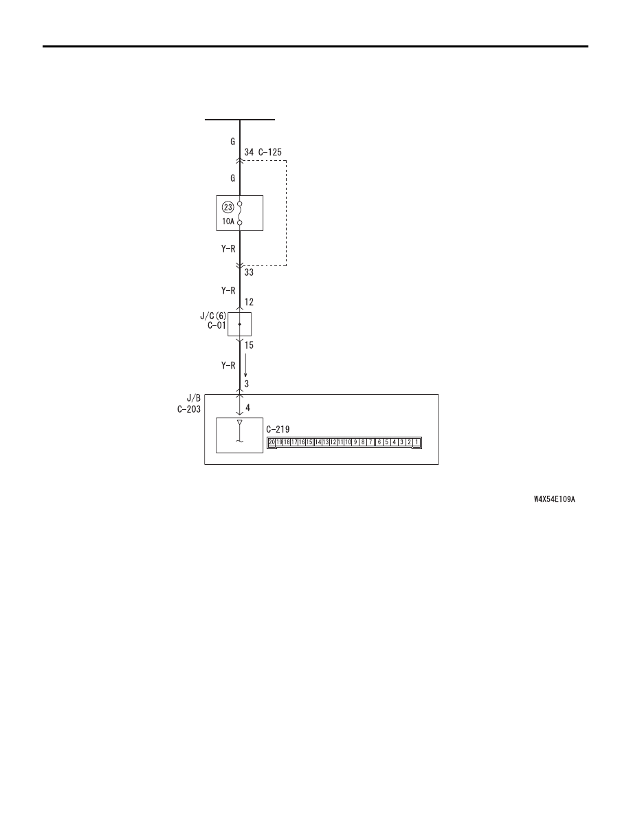
Ignition Switch (ACC) Input Circuit <RHD>

Wire colour code
B : Black     LG : Light green     G : Green     L : Blue     W : White     Y : Yellow     SB : Sky blue
BR : Brown     O : Orange     GR : Gray     R : Red     P : Pink     V : Violet

ETACS-ECU

IGNITION
SWITCH (ACC)

J/B SIDE

RELAY
BOX

INPUT SIGNAL PROCEDURES

SMART WIRING SYSTEM (SWS) NOT USING SWS MONITOR

54B-418

DIAGNOSTIC PROCEDURE

Step 1. Connector check: C-219 ETACS-ECU 
connector

Q: Is the check result normal?

YES : 

Go to Step 2.

NO : 

Repair the defective connector.

Step 2. Voltage measurement at the C-219 
ETACS-ECU connector.

(1) Remove the ETACS-ECU, and measure at the 

junction block side.

(2) Ignition switch: ACC position

(3) Voltage between C-219 ETACS-ECU connector 

terminal No.18 and body earth

OK: System voltage

Q: Is the check result normal?

YES : 

Go to Step 4.

NO : 

Go to Step 3.

AC312037

Connector: C-219

Junction block (Rear view)

Junction block side

AB

3

1

2

14

4

5

7 6

8

1110 9

1312

17

15

16

18

19

20

<LHD>

AC312047

Connector: C-219

Junction block (Rear view)

Junction block side

AB

3

1

2

14

4

5

7 6

8

1110 9

1312

17

15

16

18

19

20

<RHD>

AC312731AB

Connector C-219
(Junction block side)

2019

7

13

17

18

1615 14

10

11

12

9 8

2

6 5

3

4

1

INPUT SIGNAL PROCEDURES

SMART WIRING SYSTEM (SWS) NOT USING SWS MONITOR

54B-419

Step 3. Check the wiring harness between C-219 
ETACS-ECU connector terminal No.18 and the 
ignition switch (ACC).

NOTE: 

Prior to the wiring harness inspection, check junction 
block connector C-202, and repair if necessary.

• Check the power supply line for open circuit.

Q: Is the check result normal?

YES : 

The trouble can be an intermittent 

malfunction (Refer to GROUP 00 

− How to 

Cope with Intermittent Malfunction 

P.00-5

).

NO : 

Repair the wiring harness.

Step 4. Retest the system.
Check that the ignition switch (ACC) signal is 
received normally.

Q: Is the check result normal?

YES : 

The trouble can be an intermittent 

malfunction (Refer to GROUP 00 

− How to 

Cope with Intermittent Malfunction 

P.00-5

).

NO : 

Replace the ETACS-ECU.

AC312037

Connector: C-219

Junction block (Rear view)

Junction block side

AB

3

1

2

14

4

5

7 6

8

1110 9

1312

17

15

16

18

19

20

<LHD>

AC312047

Connector: C-219

Junction block (Rear view)

Junction block side

AB

3

1

2

14

4

5

7 6

8

1110 9

1312

17

15

16

18

19

20

<RHD>

AC312035AB

Connector: C-202

Harness side

<LHD>

Junction block (Front view)

AC312045

AB

Connector: C-202

Junction block (Front view)

Harness side

<RHD>

INPUT SIGNAL PROCEDURES

SMART WIRING SYSTEM (SWS) NOT USING SWS MONITOR

54B-420

Inspection Procedure Q-2: The ignition switch (IG1) signal is not received.

CAUTION

Whenever the ECU is replaced, ensure that the 
input signal circuit is normal.

COMMENTS ON TROUBLE SYMPTOM

Input signal from the ignition switch (IG1) is used to 
operate the functions below. If the signal is abnormal, 
these functions will not work normally.

• Lamp reminder function

• Door-ajar warning buzzer function

• Turn-signal lamp operation sound function

• Power window

• Ignition key cylinder illumination lamp

• Seat belt indicator

• Head and tail lamps

• Headlamp automatic-shutdown function

• Rear fog lamp

• Turn signal lamp

• Interior lamps

• Interior lamp automatic-shutdown function

POSSIBLE CAUSES

• Malfunction of the ETACS-ECU

• Damaged harness wires and connectors

DIAGNOSTIC PROCEDURE

Step 1. Connector check: C-219 ETACS-ECU 
connector

Q: Is the check result normal?

YES : 

Go to Step 2.

NO : 

Repair the defective connector.

Ignition Switch (IG1) Input Circuit

Wire colour code
B : Black     LG : Light green     G : Green     L : Blue     W : White     Y : Yellow     SB : Sky blue
BR : Brown     O : Orange     GR : Gray     R : Red     P : Pink     V : Violet

ETACS-ECU

IGNITION
SWITCH (IG1)

J/B SIDE

AC312037

Connector: C-219

Junction block (Rear view)

Junction block side

AB

3

1

2

14

4

5

7 6

8

1110 9

1312

17

15

16

18

19

20

<LHD>

AC312047

Connector: C-219

Junction block (Rear view)

Junction block side

AB

3

1

2

14

4

5

7 6

8

1110 9

1312

17

15

16

18

19

20

<RHD>


Content   ..  103  104  105  106   ..