Content .. 1040 1041 1042 1043 ..
Mitsubishi Grandis. Manual - part 1042
FRONT IMPACT SENSORS
SUPPLEMENTAL RESTRAINT SYSTEM (SRS)
52B-220
NOTE:
*
: indicate RHD vehicles. For LHD vehicles,
the specified application position of label is reversed
left to right.
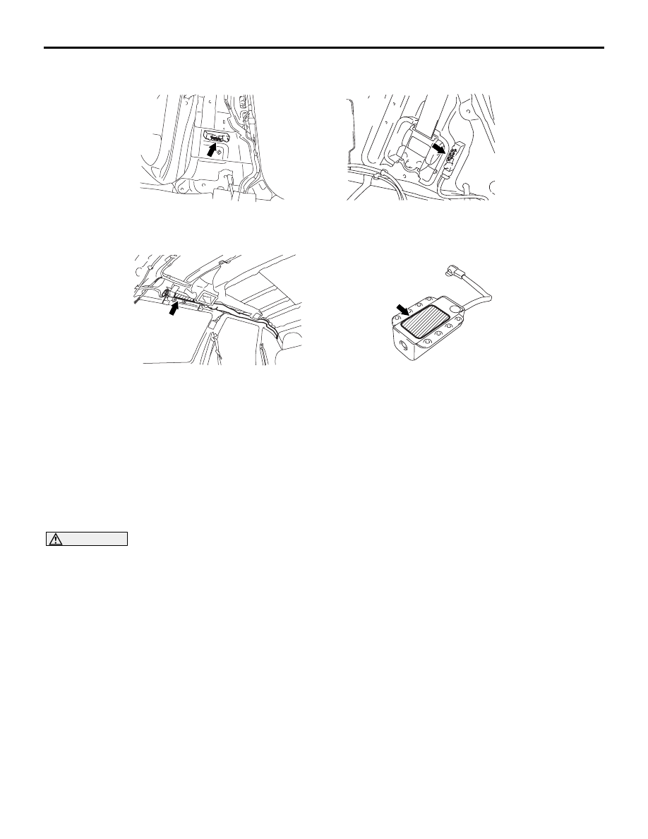
FRONT IMPACT SENSORS
REMOVAL AND INSTALLATION
M1524001500418
WARNING
•
Never repair or disassemble the front impact sensor. If faulty, replace it.
•
Do not drop or subject the front impact sensor to impact or vibration. If denting, cracking,
deformation, or rust are discovered in the front impact sensor, replace it with a new front
impact sensor. Discard the old one.
•
After deployment of an air bag, replace the front impact sensor with a new one.
AC302535
AC311616
AC311372
AC312006
AC312011
AC
Side impact sensor (front)
Side impact sensor (rear)
Curtain air bag module
Passenger's air bag
cut off switch