Mitsubishi Grandis. Manual - part 1026


  Index      Mitsubishi     Mitsubishi Grandis - service repair manual


Search            


Content   ..  1024  1025  1026  1027   ..


Mitsubishi Grandis. Manual - part 1026


TROUBLESHOOTING

SUPPLEMENTAL RESTRAINT SYSTEM (SRS)

52B-156

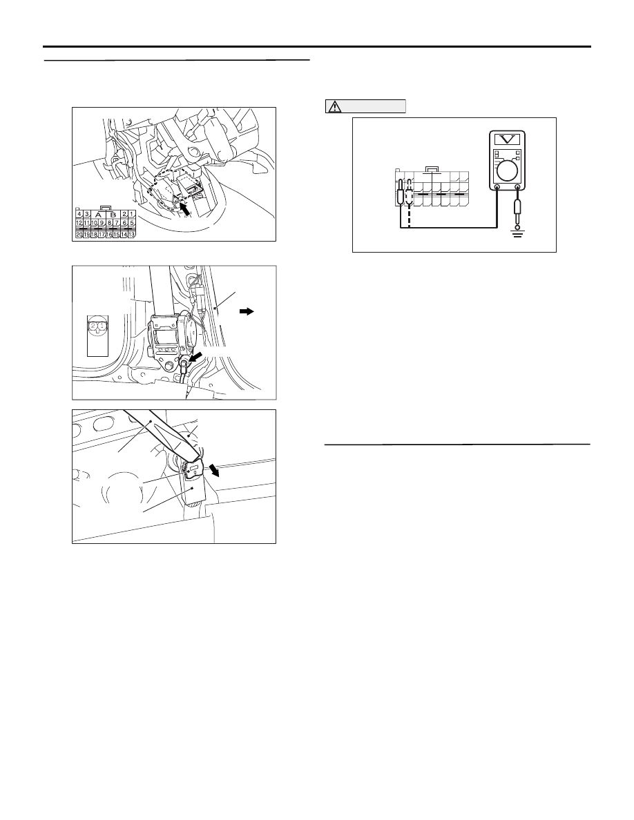
STEP 4. Check the driver's seat belt 
pre-tensioner circuit. Voltage measurement at the 
SRS-ECU connector C-120.

(1) Disconnect SRS-ECU connector C-120.

(2) Disconnect seat belt pre-tensioner (LH) 

connector D-19. Use a flat-tipped screwdriver to 
unlock the locking button at the harness side 

connector by with drawing it toward you in two 
stages, and then disconnect the connector.

(3) Turn the ignition switch to the "ON" position.

CAUTION

Do not insert a test probe into the terminal from 
its front side directly, as the connector contact 
pressure may be weakened.
(4) Measure the voltage between C-120 harness 

side connector terminals 7, 8 and body earth.

OK: 0 V

Q: Is the check result normal?

YES : 

Go to Step 5.

NO : 

Repair the harness wires between 
SRS-ECU connector C-120 (terminal No.7 
and 8) and seat belt pre-tensioner (LH) 
connector D-19 (terminal No.1 and 2). 

STEP 5. Check whether the diagnosis code is 
reset.

Q: Is diagnosis code B1473 set?

YES : 

Replace the SRS-ECU (Refer 

to

P.52B-223

).

NO : 

An intermittent malfunction is suspected 
(Refer to GROUP 00, How to Use 
Troubleshooting/Inspection Service Points 

P.00-5

). 

AC311438 AE

C-120 (Y)

Connector: C-120

Harness side
(front view)

AC302393AC

 D-19 (B)

Connector: D-19

Centre
pillar

Front vehicle

Harness side
(front view)

AC103556 AY

Locking button

Flat-tip screw
driver

D-19 Harness
side connector

D-19 Seat belt
pre-tensioner (LH)
connector

AC308187

A

B

18

10

15

7

13

5

14

6

16

8

17

9

19

11

20

12

1 2

3 4

C-120 Harness side
connector (rear view)

AD

TROUBLESHOOTING

SUPPLEMENTAL RESTRAINT SYSTEM (SRS)

52B-157

Code No.B1476: IG1 Power Supply Circuit System (Fuse No.2 Circuit) Code No.B1477: IG1 Power 
Supply Circuit System (Fuse No.3 Circuit)

Wire colour code
B : Black     LG : Light green     G : Green     L : Blue     W : White     Y : Yellow     SB : Sky blue
BR : Brown     O : Orange     GR : Gray     R : Red     P : Pink     V : Violet

IGNITION
SWITCH (IG1)

SRS-ECU

IG1 Power Supply Circuit <LH drive vehicles>

TROUBLESHOOTING

SUPPLEMENTAL RESTRAINT SYSTEM (SRS)

52B-158

CAUTION

If diagnosis code B1476 <Fuse No.2> or B1477 
<Fuse No.3> is set in the combination meter, 
always diagnose the CAN bus lines.

OPERATION

• The SRS-ECU is powered from the ignition 

switch (IG1).

• The SRS-ECU power is supplied from two 

circuits. Even if one circuit is shut off, the air bag 
can inflate.

DIAGNOSIS CODE SET CONDITIONS

This diagnosis code is set if the voltage between the 
IG1 terminals (fuse No.2 circuit or fuse No.3 circuit) 
and earth is lower than a predetermined value for a 
continuous period of 5 second or more. However, if 
the vehicle condition returns to normal, diagnosis 
code number B1476 <Fuse No.2> or B1477 <Fuse 
No.3> will be automatically erased, and the SRS 
warning light will switch off.

PROBABLE CAUSES

• Damaged wiring harnesses or connectors

• Malfunction of the SRS-ECU

Wire colour code
B : Black     LG : Light green     G : Green     L : Blue     W : White     Y : Yellow     SB : Sky blue
BR : Brown     O : Orange     GR : Gray     R : Red     P : Pink     V : Violet

IGNITION
SWITCH (IG1)

SRS-ECU

IG1 Power Supply Circuit <RH drive vehicles>

TROUBLESHOOTING

SUPPLEMENTAL RESTRAINT SYSTEM (SRS)

52B-159

DIAGNOSIS PROCEDURE

STEP 1. MUT-III CAN bus diagnostics

Use the MUT-III to diagnose the CAN bus lines.

Q: Is the check result normal?

YES : 

Go to Step 2.

NO : 

Repair the CAN bus line (Refer to GROUP 
54D, Diagnosis 

P.54D-16

).

STEP 2. Check whether the diagnosis code is 
reset.

Check again if the diagnosis code is set.
(1) Erase the diagnosis code.
(2) Ignition: LOCK (OFF) position to ON
(3) On completion, check that the diagnosis code is 

not reset.

Q: Is the diagnosis code set?

YES : 

Go to Step 3.

NO : 

There is an intermittent malfunction such as 
poor engaged connector(s) or open circuit 
(Refer to GROUP 00, How to Cope with 
Intermittent Malfunction 

P.00-5

).

STEP 3. Check junction block fuse number 2 
<B1476> or 3 <B1477>.

Q: Is the fuse burned out?

YES : 

Go to Step 6.

NO : 

Go to Step 4.

STEP 4. Check the power supply circuit for open 
circuit. Voltage measurement at SRS-ECU 
connector C-119.
(1) Disconnect the negative battery terminal.

(2) Disconnect SRS-ECU connector C-119.
(3) Connect the negative battery terminal.
(4) Turn the ignition switch to the "ON" position.

CAUTION

Do not insert a test probe into the terminal from 
its front side directly, as the connector contact 
pressure may be weakened.
(5) Measure the voltage between C-119 harness 

side connector terminal 24 <B1476> or 23 
<B1477> and body earth.

OK: 9 V or more.

Q: Is the measured voltage within the specified 

range?

YES : 

Erase the diagnosis connector memory, and 

check the diagnosis code. If diagnosis code 
B1476 or B1477 set, replace the SRS-ECU. 
(Refer to 

P.52B-223

). Then go to Step 10.

NO : 

Go to Step 5.

AC309960AC

FUSE No. 3

JUNCTION
BLOCK

FUSE No. 2

<LHD>

AC302449

AC309956AC

FUSE No. 3

JUNCTION
BLOCK

FUSE No. 2

<RHD>

AC311438 AD

C-119 (Y)

Connector: C-119

Harness side
(front view)

AC308202

42

31

38

27

21

41

28

39

22

30

25

47

36

33

44

34

45

37

48

26

29

23

40

32

43

35

46

24

B

A

C-119 Harness side
connector (rear view)

AD


Content   ..  1024  1025  1026  1027   ..