Mitsubishi Grandis. Manual - part 32


  Index      Mitsubishi     Mitsubishi Grandis - service repair manual


Search            


Content   ..  30  31  32  33   ..


Mitsubishi Grandis. Manual - part 32


SYMPTOM PROCEDURES

SMART WIRING SYSTEM (SWS) NOT USING SWS MONITOR

54B-125

COMMENTS ON TROUBLE SYMPTOM

If the power windows do not work at all, the power 
window relay, the power window main switch or the 
ETACS-ECU may be defective.

POSSIBLE CAUSES

• Malfunction of the power window relay

• Malfunction of the power window main switch

• Malfunction of the ETACS-ECU

• Damaged harness wires and connectors

DIAGNOSIS PROCEDURE

Step 1. Pulse check
Check the input signal from the ignition switch.

OK: The MUT-III sounds or the voltmeter 
needle fluctuates.

Q: Is the check result normal?

YES : 

Go to Step 2.

NO : 

Refer to inspection procedure A-2 "When 
the ignition switch is at the LOCK (OFF) 
position, the functions do not work normally. 
Check the battery power supply circuit to 
the ETACS-ECU 

P.54B-87

."

Step 2. Connector check: F-05 power window 
main switch connector

Q: Is the check result normal?

YES : 

Go to Step 3.

NO : 

Repair the connector.

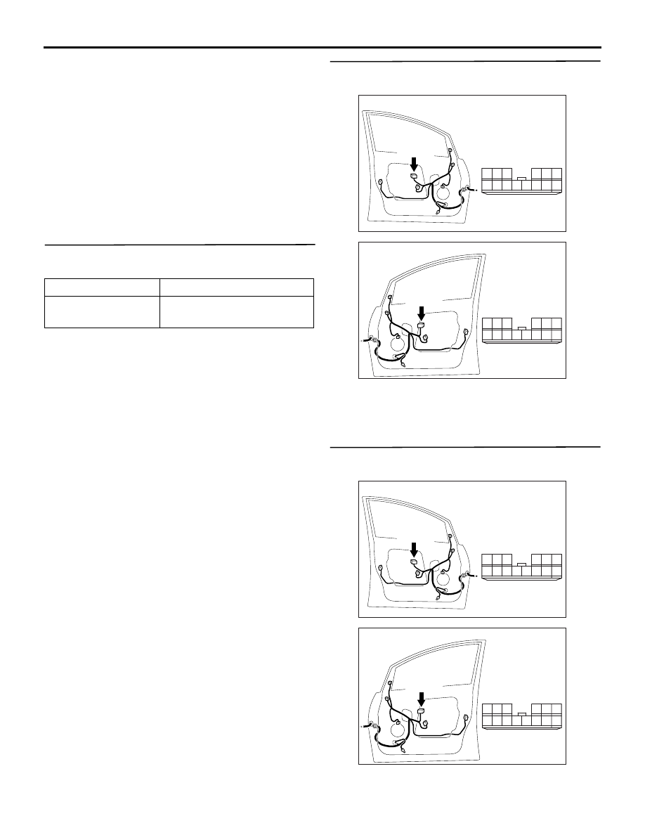
Step 3. Voltage measurement at the F-05 power 
window main switch connector.

(1) Disconnect the connector, and measure at the 

wiring harness side.

System switch

Check condition

Ignition switch (IG1) When turned from ACC to 

ON

AC311150

AB

Connector: F-05

Harness side

<LHD>

10

1

6

14

5

12

13

4

11

7

2

3

8

9

F-05(B)

AC310213

Connector: F-05

Harness side

<RHD>

10

1

6

14

5

12

13

4

11

7

2

3

8

9

F-05(B)

AB

AC311150

AB

Connector: F-05

Harness side

<LHD>

10

1

6

14

5

12

13

4

11

7

2

3

8

9

F-05(B)

AC310213

Connector: F-05

Harness side

<RHD>

10

1

6

14

5

12

13

4

11

7

2

3

8

9

F-05(B)

AB

SYMPTOM PROCEDURES

SMART WIRING SYSTEM (SWS) NOT USING SWS MONITOR

54B-126

(2) Turn the ignition switch to the ON position.

(3) Voltage between terminal 6 and body earth

OK: System voltage

Q: Is the check result normal?

YES : 

Go to Step 10.

NO : 

Go to Step 4.

Step 4. Connector check: C-217 power window 
relay connector

Q: Is the check result normal?

YES : 

Go to Step 5.

NO : 

Repair the connector.

Step 5. Check the power window relay.
Refer to GROUP 42 

− Door − On-vehicle Service 

P.42-28

.

Q: Is the check result normal?

YES : 

Go to Step 6.

NO : 

Replace the power window relay.

Step 6. Voltage measurement at C-217 power 
window relay connector.

(1) Disconnect the connector, and measure at the 

wiring harness side.

(2) Turn the ignition switch to the ON position.

(3) Voltage between terminal 5 and body earth

OK: System voltage

Q: Is the check result normal?

YES : 

Go to Step 8.

NO : 

Go to Step 7.

10

1

6

14

5

12

13

4

11

7

2

3

8

9

AC301469

Connector F-05
(Harness Side)

AC

AC310623

Connector: C-217

AB

3

4

5

1

2

Junction block side

<LHD>

Junction block (Front view)

AC310618

Connector: C-217

3

4

5

1

2

Junction block side

<RHD>

Junction block (Front view)

AB

AC310623

Connector: C-217

AB

3

4

5

1

2

Junction block side

<LHD>

Junction block (Front view)

AC310618

Connector: C-217

3

4

5

1

2

Junction block side

<RHD>

Junction block (Front view)

AB

3

4

5

1

2

AC301459AC

Connector C-217
(Junction block side)

SYMPTOM PROCEDURES

SMART WIRING SYSTEM (SWS) NOT USING SWS MONITOR

54B-127

Step 7. Check the wiring harness between C-217 
power window relay connector terminal No.5 and 
fusible link (5).

NOTE: 

Prior to the wiring harness inspection, check 
intermediate connectors C-125 and junction block 
connector C-202, and repair if necessary.

• Check the power supply line for open circuit.

Q: Is the check result normal?

YES : 

The trouble can be an intermittent 

malfunction (Refer to GROUP 00, How to 
Cope with Intermittent Malfunction 

P.00-5

).

NO : 

Repair the wiring harness.

AC310624

Connector: C-202, C-217

AB

3

4

5

1

2

Junction block side

<LHD>

Junction block (Front view)

C-217

C-202

C-217

C-202

Harness side

AC310619

Connector: C-202, C-217

AB

3

4

5

1

2

Junction block side

<RHD>

Junction block (Front view)

C-217

C-202

C-217

C-202

Harness side

AC310613

Connector: C-125 <LHD>

AI

AC310628

Connector: C-125 <RHD>

AL

SYMPTOM PROCEDURES

SMART WIRING SYSTEM (SWS) NOT USING SWS MONITOR

54B-128

Step 8. Resistance measurement at C-217 power 
window relay connector.

(1) Disconnect the connector, and measure at the 

wiring harness side.

(2) Resistance between terminal 3 and body earth

OK: 2 

 or less

Q: Is the check result normal?

YES : 

Go to Step 10.

NO : 

Go to Step 9.

Step 9. Check the wiring harness between C-217 
power window relay connector terminal No.3 and 
body earth.

NOTE: Prior to the wiring harness inspection, check 
junction block connector C-205, and repair if 
necessary.

• Check the earth wires for open circuit.

Q: Is the check result normal?

AC310623

Connector: C-217

AB

3

4

5

1

2

Junction block side

<LHD>

Junction block (Front view)

AC310618

Connector: C-217

3

4

5

1

2

Junction block side

<RHD>

Junction block (Front view)

AB

3

4

5

1

2

AC301460AC

Connector C-217
(Junction block side)

AC310624

Connector: C-205, C-217

C-205

AK

C-217

C-217

C-205

3

4

5

1

2

Junction block side

<LHD>

Harness side

AC310619

Connector: C-205, C-217

C-205

AI

C-217

C-217

C-205

3

4

5

1

2

Junction block side

Harness side

<RHD>


Content   ..  30  31  32  33   ..