Mitsubishi Grandis. Manual - part 17


  Index      Mitsubishi     Mitsubishi Grandis - service repair manual


Search            


Content   ..  15  16  17  18   ..


Mitsubishi Grandis. Manual - part 17


DIAGNOSTIC TROUBLE CODE PROCEDURES

SMART WIRING SYSTEM (SWS) NOT USING SWS MONITOR

54B-65

YES : 

The trouble can be an intermittent 

malfunction (Refer to GROUP 00 

− How to 

Cope with Intermittent Malfunction 

P.00-5

).

NO : 

Repair the wiring harness.

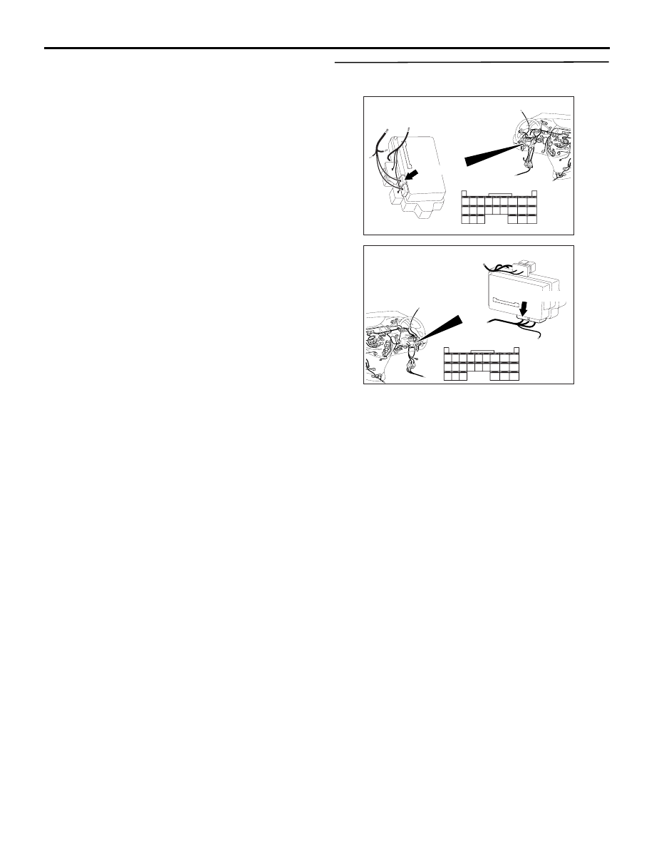
Step 16. Connector check: C-221 ETACS-ECU 
connector

Q: Is the check result normal?

YES : 

Go to Step 17.

NO : 

Repair the defective connector.

AC310626

Connector: C-221

Junction block (Rear view)

<LHD>

AC

51

52

53

54

55

56

57

58

59

60

61

62

63

64

65

66

67

68

69

70

71

72

73

74

Harness side

C-221(GR)

AC310620

Connector: C-221

Junction block 
(Rear view)

<RHD>

AC

51

52

53

54

55

56

57

58

59

60

61

62

63

64

65

66

67

68

69

70

71

72

73

74

Harness side

C-221(GR)

DIAGNOSTIC TROUBLE CODE PROCEDURES

SMART WIRING SYSTEM (SWS) NOT USING SWS MONITOR

54B-66

Step 17. Check the wiring harness between C-221 
ETACS-ECU connector terminal No.59 and F-05 
power window main switch connector terminal 
No.4.

NOTE: 

Prior to the wiring harness inspection, check 
intermediate connectors C-14 <RH drive vehicles>, 
C-27 <LH drive vehicles> and joint connector C-01, 
and repair if necessary.

• Check the communication lines for open circuit.

Q: Is the check result normal?

YES : 

Go to Step 18.

NO : 

Repair the wiring harness.

AC310626

Connector: C-221

Junction block (Rear view)

<LHD>

AC

51

52

53

54

55

56

57

58

59

60

61

62

63

64

65

66

67

68

69

70

71

72

73

74

Harness side

C-221(GR)

AC310620

Connector: C-221

Junction block 
(Rear view)

<RHD>

AC

51

52

53

54

55

56

57

58

59

60

61

62

63

64

65

66

67

68

69

70

71

72

73

74

Harness side

C-221(GR)

AC311150

AB

Connector: F-05

Harness side

<LHD>

10

1

6

14

5

12

13

4

11

7

2

3

8

9

F-05(B)

AC310213

Connector: F-05

Harness side

<RHD>

10

1

6

14

5

12

13

4

11

7

2

3

8

9

F-05(B)

AB

AC310614

Connector: C-01, C-27 <LHD>

C-27

AM

C-27

C-01

C-01

AC310632 AO

Connectors: C-01, C-14 <RHD>

C-01

C-14

C-01

C-14

DIAGNOSTIC TROUBLE CODE PROCEDURES

SMART WIRING SYSTEM (SWS) NOT USING SWS MONITOR

54B-67

Step 18. Check whether the diagnosis code is 
reset.

Replace the power window main switch, and then 
check that the diagnosis code is not reset.
(1) Replace the power window main switch.
(2) Ignition switch: ON

(3) On completion, check that diagnosis code No.05 

is not reset.

Q: Is diagnosis code No.05 set?

YES : 

Replace the ETACS-ECU.

NO : 

The procedure is complete.

Diagnosis code No.10 Bus off

CAUTION

If diagnosis code No.10 is set in the ETACS-ECU, 
diagnose the CAN bus lines.

CAUTION

Whenever the ECU is replaced, ensure that the 
input and output signal circuits are normal.

TROUBLE JUDGMENT

Diagnosis code No.10 will be stored when the 
ETACS-ECU ceases CAN communication (bus off) 
and then resumes the communication by turning the 
ignition switch to the "LOCK" (OFF) position.

COMMENTS ON TROUBLE SYMPTOM

The wiring harness wire or connectors may have 
loose, corroded, or damage terminals, or terminals 
pushed back in the connector, or the SWS 
communication lines may be defective.

POSSIBLE CAUSES

Damaged harness wires and connectors

DIAGNOSIS PROCEDURE

Step 1. MUT-III CAN bus diagnostics

Use the MUT-III to diagnose the CAN bus lines.

Q: Is the check result normal?

YES : 

Go to Step 2.

NO : 

Repair the CAN bus line (Refer to GROUP 
54D 

− Diagnosis 

P.54D-16

). On completion, 

go to Step 3.

Step 2. Check whether the diagnosis code is 
reset.

Check again if the diagnosis code is set.
(1) Erase the diagnosis code.
(2) Ignition: LOCK (OFF) position to ON
(3) On completion, check that the diagnosis code is 

not reset.

Q: Is the check result normal?

YES : 

If a trouble is solved, it is determined that 

there is an intermittent malfunction such as 
poor engaged connector(s) or open circuit 
(Refer to GROUP 00 

− How to use 

troubleshooting/Inspection Service Points 

P.00-5

).

NO : 

Replace the ETACS-ECU, and then go to 
Step 3.

Step 3. Check whether the diagnosis code is 
reset.

Recheck if the diagnosis code is set.
(1) Erase the diagnosis code.
(2) Ignition switch: LOCK (OFF) position to ON
(3) Check if the diagnosis code is set.

Q: Is the check result normal?

YES : 

The procedure is complete.

NO : 

Return to Step 1.

DIAGNOSTIC TROUBLE CODE PROCEDURES

SMART WIRING SYSTEM (SWS) NOT USING SWS MONITOR

54B-68

Diagnosis code No.11 Engine-A/T-ECU time-out (related to engine)

CAUTION

If diagnosis code No.11 is set in the ETACS, 
diagnose the CAN main bus line.

CAUTION

Whenever the ECU is replaced, ensure that the 
communication circuit is normal.

TROUBLE JUDGMENT

• The ETACS-ECU receives engine and 

transmission control signals from the 
engine-A/T-ECU <A/T> or the engine-ECU 
<M/T> through the CAN bus lines. If the ECU can 
not receive the engine control signal at all, 
diagnosis code No.11 will be set.

COMMENTS ON TROUBLE SYMPTOM

Current trouble

• Connector(s) or wiring harness in the CAN bus 

lines between the ETACS-ECU and the 
engine-A/T-ECU <A/T> or the engine-ECU 
<M/T>, the power supply circuits to these ECUs, 
or the ETACS-ECU itself may be defective.

Past trouble

• If diagnosis code No.11 is set as past trouble, 

carry out diagnosis with particular emphasis on 
wiring and connector(s) in the CAN bus lines 
between the ETACS-ECU and the 
engine-A/T-ECU <A/T> or the engine-ECU 
<M/T>, or power supply to the engine-A/T-ECU 
<A/T> or the engine-ECU <M/T>. For diagnosis 
procedures, refer to "How to treat past trouble" 
(Refer to GROUP 00 

− How to Use 

Troubleshooting/Inspection Service Points 

P.00-5

).

NOTE: For a past trouble, you can not find it by the 

MUT-III CAN bus diagnostics even if there is any 
failure in CAN bus lines. In this case, refer to 
GROUP 00, How to Use 
Troubleshooting/Inspection Service Points 

P.00-5


and check the CAN bus lines. You can narrow 
down the possible cause of the trouble by 
referring to the diagnosis code, which is set 
regarding the CAN communication-linked ECUs 
(Refer to GROUP 54D 

 CAN Bus Line 

Diagnostic Flow 

P.54D-9

).

POSSIBLE CAUSES

• Malfunction of the engine-A/T-ECU <A/T> or 

engine-ECU <M/T>

• Malfunction of the ETACS-ECU

• Malfunction of the CAN bus

DIAGNOSTIC PROCEDURE

Step 1. MUT-III CAN bus diagnostics
Use the MUT-III to diagnose the CAN bus lines.

Q: Is the check result normal?

YES : 

Go to Step 2.

NO : 

Repair the CAN bus line (Refer to GROUP 
54D 

− Diagnosis 

P.54D-16

). Repair the 

CAN bus line and go to Step 6.

Step 2. Check for engine control diagnosis code.
Check whether the engine control-related diagnosis 
code is set.

Q: Is the check result normal?

YES : 

Go to Step 3.

NO : 

Engine (Refer to GROUP 13A 

− 

Troubleshooting 

P.13A-11

).

Step 3. MUT-III diagnosis code
Check if a diagnosis code, which relates to CAN 
communication-linked systems below, is set.

• Combination meter

U1100: Engine-related time-out diagnosis code

• Multi-display

U1100: Engine-related time-out diagnosis code

Q: Is the check result normal?

YES : 

Go to Step 5.

NO : 

Go to Step 4.

Step 4. Check whether the diagnosis code is 
reset.
Check again if the diagnosis code is set.
(1) Erase the diagnosis code.
(2) Ignition switch: LOCK (OFF) position to ON
(3) On completion, check that the diagnosis code is 

not reset.

Q: Is the check result normal?

YES : 

A poor connection, open circuit or other 

intermittent malfunction is present in the 
CAN bus lines between the engine-A/T-ECU 
<A/T> or the engine-ECU <M/T> and the 
ETACS-ECU (Refer to GROUP 00 

− How to 

Use Troubleshooting/Inspection Service 
Points 

P.00-5

).

NO : 

Replace the engine-A/T-ECU, and then go 
to Step 6.


Content   ..  15  16  17  18   ..