Mitsubishi L200. Manual - part 892


  Index      Mitsubishi     Mitsubishi L200 - service repair manual 2012 year


Search            


Content   ..  890  891  892  893   ..


Mitsubishi L200. Manual - part 892


Mode selection damper control 
motor removal step 

Lower panel assembly (Refer to 
GROUP 52A, Instrument Panel .)

1.

Mode selection damper control 
motor and potentiometer
Air mixing damper control motor 
removal step 

Glove box (Refer to GROUP 52A, 
Instrument Panel .)

2.

Air mixing damper control motor 
and potentiometer
Power transistor removal step 

3.

Power transistor
Outside/inside air selection 
damper control motor removal 
step 

Glove box (Refer to GROUP 52A, 
Instrument Panel .)

4.

Outside/inside air selection damper 
control motor

MODE SELECTION DAMPER CONTROL MOTOR, AIR MIXING DAMPER CONTROL MOTOR AND POWER 

AUTOMATIC AIR CONDITIONER

55B-97

INSPECTION

M1552014304543

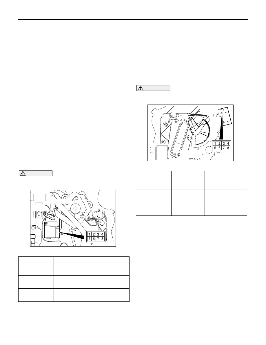
CHECK THE MODE SELECTION DAMPER 
CONTROL MOTOR AND POTENTIOME-
TER

CAUTION

Stop energizing when the lever is set to the oper-
ation stopping position.

AC510127

AB

DEF position

FACE 
position

MOTOR CHECK

Battery 
connection 
(+) terminal

Battery 
connection (-
) terminal

Lever operation

3

1

Rotate to the DEF 
side

1

3

Rotate to the 
FACE side

Potentiometer check
When the resistance value between connector termi-
nals 2 and 6 is measured while checking the motor, 
check that the resistance value changes gradually 
within the standard value.

Standard value: 1.20 (FACE) 

 4.80 (DEF) k

CHECK THE AIR MIXING DAMPER CON-
TROL MOTOR AND POTENTIOMETER

CAUTION

Stop energizing when the lever is set to the oper-
ation stopping position.

AC510215

Air mixing
damper lever

MAX HOT
position

MAX COOL
position

AB

MOTOR CHECK

Battery 
connection 
(+) terminal

Battery 
connection (-
) terminal

Lever operation

3

1

Rotate to the HOT 
side.

1

3

Rotate to the 
COOL side.

Potentiometer check
When the resistance value between connector termi-
nals 2 and 6 is measured while checking the motor, 
check that the resistance value changes gradually 
within the standard value.

Standard value: 1.20 (MAX HOT) 

 4.80 (MAX 

COOL) k

SENSORS

AUTOMATIC AIR CONDITIONER

55B-98

CHECK THE OUTSIDE/INSIDE AIR 
SELECTION DAMPER CONTROL MOTOR

CAUTION

Stop energizing when the lever is set to the oper-
ation stopping position.

AC510128

Outside

Inside

AB

MOTOR CHECK

Battery 
connection 
(+) terminal

Battery 
connection (-
) terminal

Lever operation

1

4

Rotate to the HOT 
side.

1

3

Rotate to the 
COOL side.

SENSORS

REMOVAL AND INSTALLATION

M1554017500120

AC600186

AL

1

Removal steps 

Radiator grille (Refer to GROUP 
51, Radiator grille ).

1.

Ambient temperature sensor

REMOVAL AND INSTALLATION

M1554001900538

AC903722

2

1

AC

Interior temperature sensor 
removal steps 

Glove box (Refer to GROUP 52A, 
Instrument Panel ).

1.

Interior temperature sensor

2.

Aspirator hose

OTHER PARTS

AUTOMATIC AIR CONDITIONER

55B-99

INSPECTION

M1552014304899

AMBIENT TEMPERATURE SENSOR

AC601429AE

10

12

14

16

8

6

4

2

0

10

20

30 40

50

–10

0

Resistance

(k )

Temperature (˚C)

Check to see that the resistance shown in the graph 
is almost satisfied when measuring the resistance 
between the sensor terminals under two or more dif-
ferent temperature conditions.

INTERIOR TEMPERATURE SENSOR

AC209192AE

10

8

6

4

2

0

10

20

30

40

–10

0

Resistance

(k )

Temperature (˚C)

Check to see that the resistance shown in the graph 
is almost satisfied when measuring the resistance 
between the sensor terminals under two or more dif-
ferent temperature conditions.

OTHER PARTS

OTHER PARTS

M1554004000705

The other service procedures and components are 
the same as the heater and the manual A/C.

• On-vehicle service

• Blower assembly

• Blower motor and outside/inside air selection 

damper control motor

• Compressor

• Condenser assembly

• Refrigerant line

• Ducts

• Ventilators


Content   ..  890  891  892  893   ..