Mitsubishi L200. Manual - part 887


  Index      Mitsubishi     Mitsubishi L200 - service repair manual 2012 year


Search            


Content   ..  885  886  887  888   ..


Mitsubishi L200. Manual - part 887


TROUBLESHOOTING

AUTOMATIC AIR CONDITIONER

55B-77

STEP 13. Check the wiring harness between A-
140X PTC heater relay 1 connector terminal No.2 
and the fusible link (25).

AC509815

A-140X

Connector: A-140X

AB

Relay box side

• Check the PTC heater relay 1 power supply line 

for open circuit.

Q: Is the check result normal?

YES : 

The trouble can be an intermittent 

malfunction (Refer to GROUP 00, How to 
Cope with Intermittent Malfunction ).

NO : 

Repair the wiring harness.

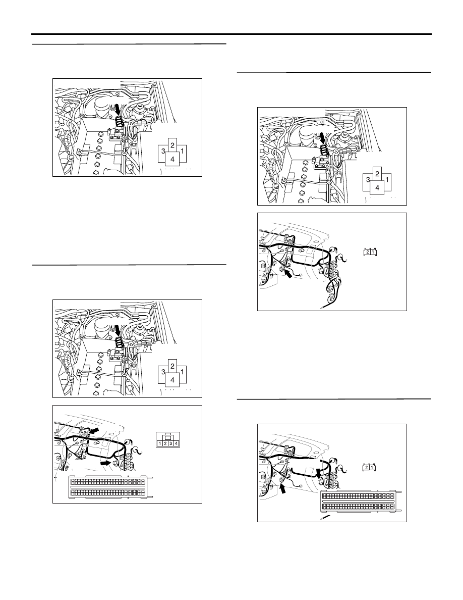
STEP 14. Check the wiring harness between A-
140X PTC heater relay 1 connector terminal No.1 
and C-105 engine-ECU connector terminal No.38.

AC509815

A-140X

Connector: A-140X

AB

Relay box side

AC509613CG

Connectors: C-105, C-148 <LHD>

C-148

C-148

C-105

C-105 (B)

35

40

41

42

1817

38

39

15

16

14

3736

12

13

11

32

8

3433

9

10

30

31

7 6

29

5

4

28

3

27

2

26

1

25

19
43

2120

22

23

46

47

4544

24
48

76

52

86

62

63

64

65

66

67

68

69

70

71

72

92

95

96

93

94

89

90

91

8887

53

54

55

56

57

58

59

60

61

83

8584

8281

78

79

80

77

49

50

51

74

75

73

Harness side

NOTE: Prior to the wiring harness inspection, check 
intermediate connector C-148, and repair if neces-
sary.

• Check the PTC heater relay 1 earth line for open 

and short circuit.

Q: Is the check result normal?

YES : 

Go to Step 15.

NO : 

Repair the wiring harness.

STEP 15. Check the wiring harness between A-
140X PTC heater relay 1 connector terminal No.4 
and C-149 PTC heater connector terminal No.2.

AC509815

A-140X

Connector: A-140X

AB

Relay box side

AC509613AT

Harness side

Connector: C-149 <LHD>

C-149 (GR)

• Check the PTC heater relay 1 power supply line 

for open circuit.

Q: Is the check result normal?

YES : 

The trouble can be an intermittent 

malfunction (Refer to GROUP 00, How to 
Cope with Intermittent Malfunction ).

NO : 

Repair the wiring harness.

STEP 16. Voltage measurement at C-150 PTC 
heater 2 connector.

AC509613 CH

Harness side

Connectors: C-105, C-150 <LHD>

35

40

41

42

1817

38

39

15

16

14

3736

12

13

11

32

8

3433

9

10

30

31

7 6

29

5

4

28

3

27

2

26

1

25

19
43

2120

22

23

46

47

4544

24
48

76

52

86

62

63

64

65

66

67

68

69

70

71

72

92

95

96

93

94

89

90

91

8887

53

54

55

56

57

58

59

60

61

83

8584

8281

78

79

80

77

49

50

51

74

75

73

C-150 (GR)

C-105 (B)

C-150

C-105

Harness side

(1) Disconnect the connector, and measure at the 

wiring harness side.

TROUBLESHOOTING

AUTOMATIC AIR CONDITIONER

55B-78

(2) Turn the ignition switch to the "ON" position.

ACA00423

35

40

41

42

1817

38

39

15

16

14

3736

12

13

11

32

8

3433

9

10

30

31

7 6

29

5

4

28

3

27

2

26

1

25

19
43

2120

22

23

46

47

4544

24
48

76

52

86

62

63

64

65

66

67

68

69

70

71

72

92

95

96

93

94

89

90

91

8887

53

54

55

56

57

58

59

60

61

83

8584

8281

78

79

80

77

49

50

51

74

75

73

Connector C-105 
(Harness side)

AF

(3) Disconnect engine-ECU connector C-105 and 

earth terminal 41.

AC310507

Connector C-150 
(Harness side)

JE

(4) Voltage between terminal 2 and body earth.

OK: System voltage

Q: Is the check result normal?

YES : 

Go to Step 25.

NO : 

Go to Step 17.

STEP 17. Connector check: A-141X PTC heater 
relay 2 controller connector

AC509815

A-141X

Connector: A-141X

AD

Relay box side

Q: Is the check result normal?

YES : 

Go to Step 18.

NO : 

Repair the connector.

STEP 18. Check the PTC heater relay 2 
continuity.
 Refer to .

Q: Is the PTC heater relay 2 in good condition?

YES : 

Go to Step 19.

NO : 

Replace the PTC heater relay 2.

STEP 19. Voltage measurement at A-141X PTC 
heater relay 2 connector.

AC509815

A-141X

Connector: A-141X

AD

Relay box side

(1) Remove the relay, and measure at the relay block 

side.

(2) Turn the ignition switch to the "ON" position.

AC310507

Connector C-141X
(Junction block side)

JZ

(3) Voltage between terminal 3 and body earth.

OK: System voltage

Q: Is the check result normal?

YES : 

Go to Step 21.

NO : 

Go to Step 20.

TROUBLESHOOTING

AUTOMATIC AIR CONDITIONER

55B-79

STEP 20. Check the wiring harness between A-
141X PTC heater relay 2 connector terminal No.3 
and the ignition switch (IG2).

AC509815

A-141X

Connector: A-141X

AD

Relay box side

NOTE: 

AC509975AH

Connector: A-28

A-28 (B)

AC509613AW

Connector: C-148 <LHD>

AC509934BD

Connector: C-207<LHD>

Harness side

Junction block (Front view)

Prior to the wiring harness inspection, check junction 
block connectors C-207 and C-210, intermediate 
connector A-28 and C-148, and repair if necessary.

• Check the PTC heater relay 2 power supply line 

for open circuit.

Q: Is the check result normal?

YES : 

The trouble can be an intermittent 

malfunction (Refer to GROUP 00, How to 
Cope with Intermittent Malfunction .)

NO : 

Repair the wiring harness.

STEP 21. Voltage measurement at A-141X PTC 
heater relay 2 connector.

AC509815

A-141X

Connector: A-141X

AD

Relay box side

(1) Remove the relay, and measure at the relay block 

side.

AC310507

Connector C-141X
(Junction block side)

KA

(2) Voltage between terminal 2 and body earth.

OK: System voltage

Q: Is the check result normal?

YES : 

Go to Step 23.

NO : 

Go to Step 22.

TROUBLESHOOTING

AUTOMATIC AIR CONDITIONER

55B-80

STEP 22. Check the wiring harness between A-
141X PTC heater relay 2 connector terminal No.2 
and the fusible link (25).

AC509815

A-141X

Connector: A-141X

AD

Relay box side

• Check the PTC heater relay 2 power supply line 

for open circuit.

Q: Is the check result normal?

YES : 

The trouble can be an intermittent 

malfunction (Refer to GROUP 00, How to 
Cope with Intermittent Malfunction ).

NO : 

Repair the wiring harness.

STEP 23. Check the wiring harness between A-
141X PTC heater relay 2 connector terminal No.1 
and C-105 engine-ECU connector terminal No.41.

AC509815

A-141X

Connector: A-141X

AD

Relay box side

AC509613CG

Connectors: C-105, C-148 <LHD>

C-148

C-148

C-105

C-105 (B)

35

40

41

42

1817

38

39

15

16

14

3736

12

13

11

32

8

3433

9

10

30

31

7 6

29

5

4

28

3

27

2

26

1

25

19
43

2120

22

23

46

47

4544

24
48

76

52

86

62

63

64

65

66

67

68

69

70

71

72

92

95

96

93

94

89

90

91

8887

53

54

55

56

57

58

59

60

61

83

8584

8281

78

79

80

77

49

50

51

74

75

73

Harness side

NOTE: Prior to the wiring harness inspection, check 
intermediate connector C-148, and repair if neces-
sary.

• Check the PTC heater relay 2 earth line for open 

and short circuit.

Q: Is the check result normal?

YES : 

Go to Step 24.

NO : 

Repair the wiring harness.

STEP 24. Check the wiring harness between A-
141X PTC heater relay 2 connector terminal No.4 
and C-150 PTC heater connector terminal No.2.

AC509815

A-141X

Connector: A-141X

AD

Relay box side

AC509613 CD

Harness side

C-105 (B)

Connector: C-105 <LHD>

35

40

41

42

1817

38

39

15

16

14

3736

12

13

11

32

8

3433

9

10

30

31

7 6

29

5

4

28

3

27

2

26

1

25

19
43

2120

22

23

46

47

4544

24
48

76

52

86

62

63

64

65

66

67

68

69

70

71

72

92

95

96

93

94

89

90

91

8887

53

54

55

56

57

58

59

60

61

83

8584

8281

78

79

80

77

49

50

51

74

75

73

• Check the PTC heater power supply line for open 

circuit.

Q: Is the check result normal?

YES : 

The trouble can be an intermittent 

malfunction (Refer to GROUP 00, How to 
Cope with Intermittent Malfunction .)

NO : 

Repair the wiring harness.

STEP 25. Connector check: C-43 A/C-ECU 
connector

AC509611AR

Connector: C-43 <LHD>

Harness side

Q: Is the check result normal?

YES : 

Go to Step 26.

NO : 

Repair the connector.


Content   ..  885  886  887  888   ..