Mitsubishi L200. Manual - part 848


  Index      Mitsubishi     Mitsubishi L200 - service repair manual 2012 year


Search            


Content   ..  846  847  848  849   ..


Mitsubishi L200. Manual - part 848


TROUBLESHOOTING

HEATER, AIR CONDITIONER AND VENTILATION

55A-8

DIAGNOSIS PROCEDURE

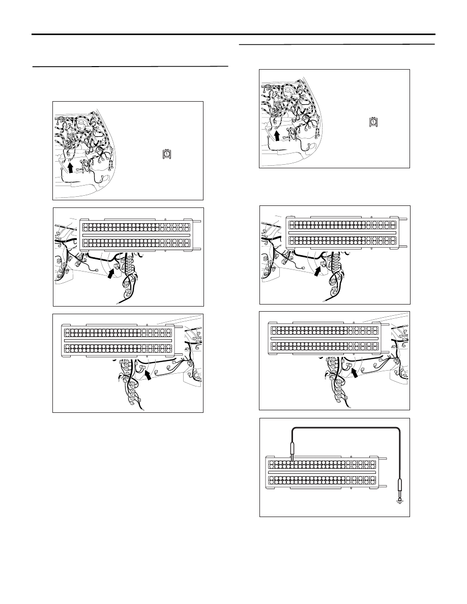
STEP 1. Connector check: A-33 A/C compressor 
and clutch assembly connector and C-105 
engine-ECU

AC509975AT

Harness side

Connector: A-33

A-33 (B)

AC509613 CB

Harness side

C-105 (B)

Connector: C-105 <LHD>

35

40

41

42

1817

38

39

15

16

14

3736

12

13

11

32

8

3433

9

10

30

31

7 6

29

5

4

28

3

27

2

26

1

25

19
43

2120

22

23

46

47

4544

24
48

76

52

86

62

63

64

65

66

67

68

69

70

71

72

92

95

96

93

94

89

90

91

8887

53

54

55

56

57

58

59

60

61

83

8584

8281

78

79

80

77

49

50

51

74

75

73

AC509930 CA

C-105 (B)

Connector: C-105 <RHD>

Harness side

35

40

41

42

1817

38

39

15

16

14

3736

12

13

11

32

8

3433

9

10

30

31

7 6

29

5

4

28

3

27

2

26

1

25

19
43

2120

22

23

46

47

4544

24
48

76

52

86

62

63

64

65

66

67

68

69

70

71

72

92

95

96

93

94

89

90

91

8887

53

54

55

56

57

58

59

60

61

83

8584

8281

78

79

80

77

49

50

51

74

75

73

Q:  Is the check result normal?

YES : 

Go to Step 2.

NO : 

Repair the connector.

STEP 2. Voltage measurement at A-33 A/C 
compressor and clutch assembly connector.

AC509975AT

Harness side

Connector: A-33

A-33 (B)

(1) Disconnect the connector, and measure at the 

wiring harness side.

(2) Turn the ignition switch to the "ON" position.

AC509613 CD

Harness side

C-105 (B)

Connector: C-105 <LHD>

35

40

41

42

1817

38

39

15

16

14

3736

12

13

11

32

8

3433

9

10

30

31

7 6

29

5

4

28

3

27

2

26

1

25

19
43

2120

22

23

46

47

4544

24
48

76

52

86

62

63

64

65

66

67

68

69

70

71

72

92

95

96

93

94

89

90

91

8887

53

54

55

56

57

58

59

60

61

83

8584

8281

78

79

80

77

49

50

51

74

75

73

AC509930 CA

C-105 (B)

Connector: C-105 <RHD>

Harness side

35

40

41

42

1817

38

39

15

16

14

3736

12

13

11

32

8

3433

9

10

30

31

7 6

29

5

4

28

3

27

2

26

1

25

19
43

2120

22

23

46

47

4544

24
48

76

52

86

62

63

64

65

66

67

68

69

70

71

72

92

95

96

93

94

89

90

91

8887

53

54

55

56

57

58

59

60

61

83

8584

8281

78

79

80

77

49

50

51

74

75

73

ACA00423

35

40

41

42

1817

38

39

15

16

14

3736

12

13

11

32

8

3433

9

10

30

31

7 6

29

5

4

28

3

27

2

26

1

25

19
43

2120

22

23

46

47

4544

24
48

76

52

86

62

63

64

65

66

67

68

69

70

71

72

92

95

96

93

94

89

90

91

8887

53

54

55

56

57

58

59

60

61

83

8584

8281

78

79

80

77

49

50

51

74

75

73

Connector C-105 
(Harness side)

AB

(3) Disconnect engine-ECU connector C-105 and 

TROUBLESHOOTING

HEATER, AIR CONDITIONER AND VENTILATION

55A-9

earth terminal 19.

AC402679

Connector A-33 
(Harness side)

CE

(4) Voltage between terminal 1 and body earth.

OK: System voltage

Q: Is the check result normal?

YES : 

Go to Step 3.

NO : 

Refer to Inspection Procedure 4 " The A/C 
compressor and clutch assembly does not 
work 

P.55A-30

 ".

STEP 3. Check that the blower motor operates 
when the blower switch is moved to the "4 (HI)" 
position.
(1) Turn the ignition switch to the "ON" position.
(2) Turn the blower switch to the "4 (HI) " position.

Q: Does the blower motor operate when the blower 

switch is moved to the "4 (HI)" position?
YES : 

Go to Step 4.

NO : 

Refer to Inspection procedure 2 "The blower 
does not work 

P.55A-17

."

STEP 4. Resistance measurement at the C-05 A/C 
switch module connector.

AC509611AV

Connector: C-05 <LHD>

Harness side

AC509932 BA

Harness side

Connector: C-05 <RHD>

(1) Disconnect the connector, and measure at the 

wiring harness side.

AC403234

Connector C-05 
(Harness side)

CD

(2) Measure the resistance between terminal 5 and 

body earth.

OK: Continuity (Less than 2

)

Q: Is the check result normal?

YES : 

 Go to Step 6.

NO : 

Go to Step 5.

TROUBLESHOOTING

HEATER, AIR CONDITIONER AND VENTILATION

55A-10

STEP 5. Check the wiring harness between C-05 
A/C switch module connector terminal No.5 and 
body earth.

AC509611AV

Connector: C-05 <LHD>

Harness side

AC509932 BA

Harness side

Connector: C-05 <RHD>

• Check the A/C switch module earth line for open 

circuit.

Q: Is the check result normal?

YES : 

The trouble can be an intermittent 

malfunction (Refer to GROUP 00, How to 
Cope with Intermittent Malfunction ).

NO : 

Repair the wiring harness.

STEP 6. Voltage measurement at C-05 A/C switch 
module connector.

AC509611AV

Connector: C-05 <LHD>

Harness side

AC509932 BA

Harness side

Connector: C-05 <RHD>

(1) Disconnect the connector, and measure at the 

wiring harness side.

(2) Turn the ignition switch to the "ON" position.

AC402679

Connector C-05 
(Harness side)

CF

(3) Measure the voltage between terminal 10 and 

body earth.

OK: System voltage

Q: Is the check result normal?

YES : 

Go to Step 8.

NO : 

Go to Step 7.

TROUBLESHOOTING

HEATER, AIR CONDITIONER AND VENTILATION

55A-11

STEP 7. Check the wiring harness between C-05 
A/C switch module connector terminal No.10 and 
the ignition switch (IG2).

AC509611AV

Connector: C-05 <LHD>

Harness side

AC509932 BA

Harness side

Connector: C-05 <RHD>

NOTE: 

AC509934 AS

Connectors: C-207, C-209 <LHD>

Harness side

C-209

C-207

Harness side

C-209

C-207

Junction block (Front view)

AC509936 AN

Connectors: C-207, C-209 <RHD>

Harness side

C-209

C-207

Harness side

C-209

C-207

Junction block (Front view)

Prior to the wiring harness inspection, check junction 
block connector C-209 and C-207, and repair if nec-
essary.

• Check the blower relay power supply line for 

open circuit.

Q: Is the check result normal?

YES : 

The trouble can be an intermittent 

malfunction (Refer to GROUP 00, How to 
Cope with Intermittent Malfunction ).

NO : 

Repair the wiring harness.

STEP 8. Connector check: C-06 blower switch 
connector

AC509611AW

Connector: C-06 <LHD>

Harness side

AC509932 BB

Harness side

Connector: C-06 <RHD>

Q: Is the check result normal?

YES : 

Go to Step 9.

NO : 

Repair the connector.


Content   ..  846  847  848  849   ..