Mitsubishi L200. Manual - part 827
TROUBLESHOOTING
CONTROLLER AREA NETWORK (CAN)
54C-67
<RHD> intermediate connector terminal Nos.6
and 7
OK: 120
± 20 Ω
Q: Is the check result normal?
YES :
<Within 120
± 20 Ω> Go to Step 3.
NO :
<Not within 120
± 20 Ω> Go to Step 8.
STEP 3. Connector check: C-01 joint connector
(CAN2)
AC903853
BL
Connector: C-01 <LHD>
C-01 (L)
AC903865AU
Connector: C-01 <RHD>
C-01 (L)
CAUTION
The strand end of the twist wire should be within
10 cm from the connector. For details refer to
.
AC209350
1
12
2
13
3
14
4
15
5
16
6
17
7
18
8
19
9
20
10
21
11
22
AC209350
1
12
2
13
3
14
4
15
5
16
6
17
7
18
8
19
9
20
10
21
11
22
AC
Short pin
When checking the joint connector, ensure that its
wiring harness side and its short pins are not dam-
aged.
Q: Is the check result normal?
YES :
Go to Step 4.
NO :
Repair a defective connector or replace the
joint connector.
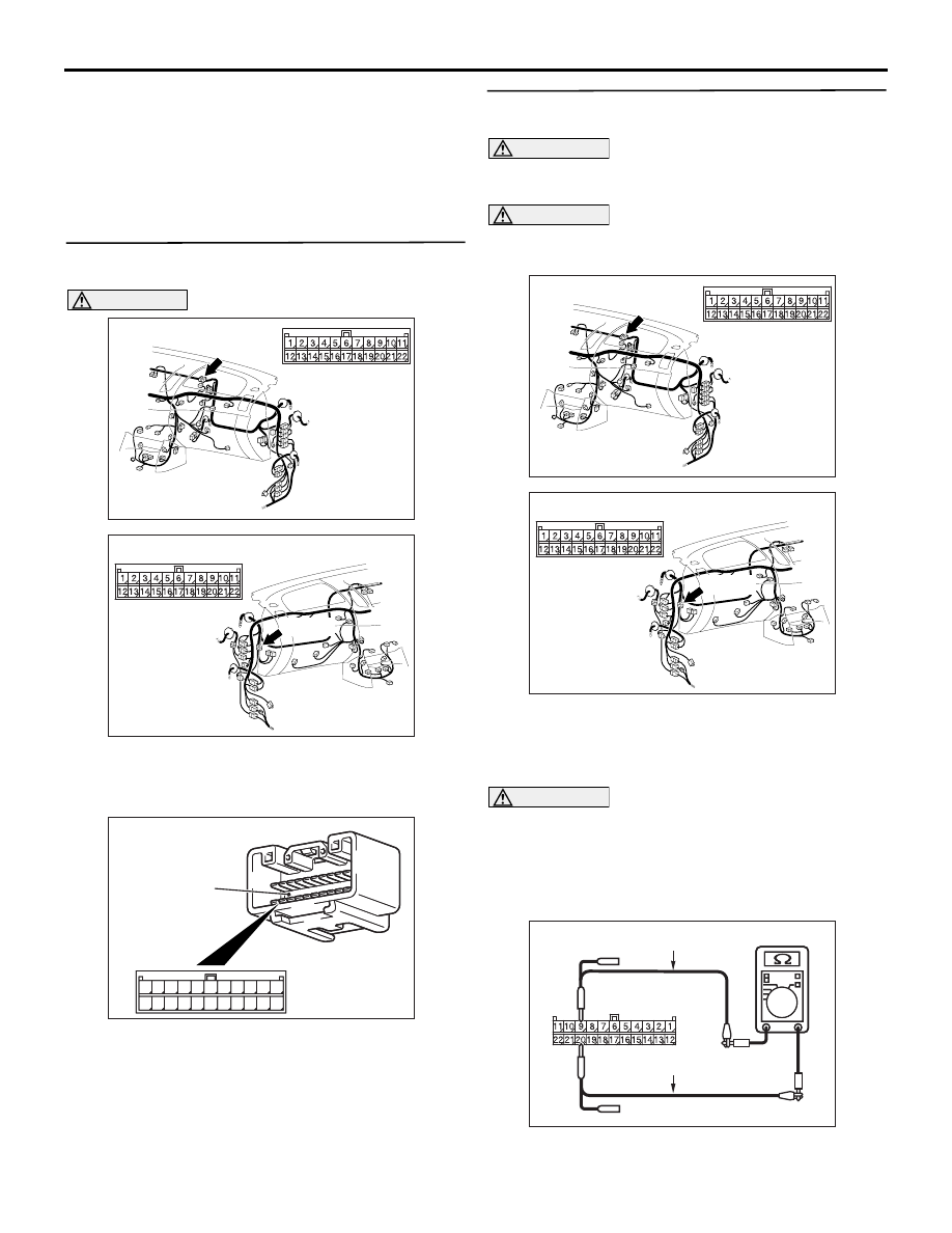
STEP 4. Resistance measurement at C-01 joint
connector (CAN2).
CAUTION
A digital multimeter should be used. For details
refer to
CAUTION
The test wiring harness should be used. For
details refer to
.
AC903853
BL
Connector: C-01 <LHD>
C-01 (L)
AC903865AU
Connector: C-01 <RHD>
C-01 (L)
(1) Disconnect the connector, and measure at the
wiring harness side.
(2) Turn the ignition switch to the LOCK (OFF)
position.
CAUTION
When measuring the resistance, disconnect the
negative battery terminal. For details refer to
.
(3) Ensure that the negative battery terminal is
disconnected.
AC204738
AC204738MA
Harness side: C-01
Test harness
Test harness
(4) Resistance between C-01 joint connector (CAN2)