Mitsubishi L200. Manual - part 805


  Index      Mitsubishi     Mitsubishi L200 - service repair manual 2012 year


Search            


Content   ..  803  804  805  806   ..


Mitsubishi L200. Manual - part 805


DIAGNOSIS CODE PROCEDURES

LOCAL INTERCONNECT NETWORK (LIN)

54B-31

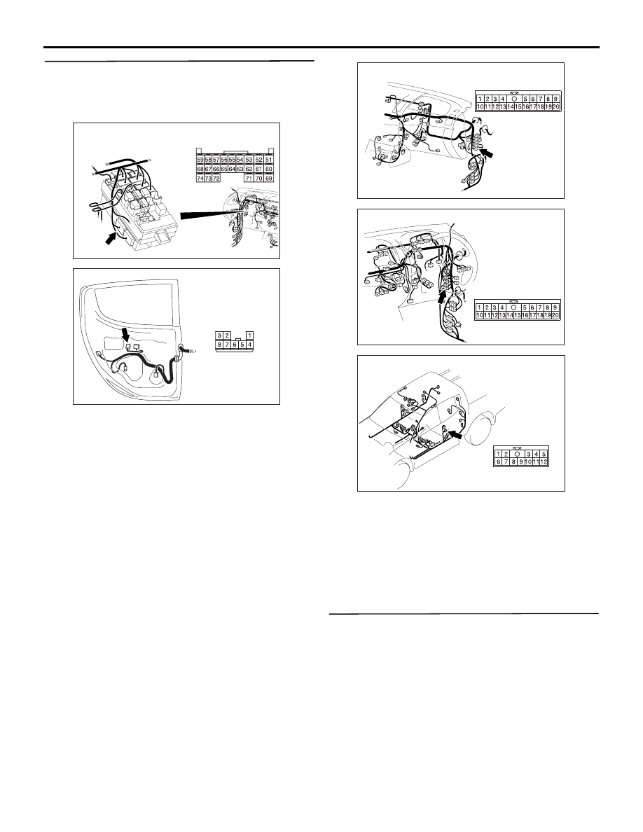
STEP 6. Check the wiring harness between C-219 
ETACS-ECU connector terminal No.54 and E-13 
rear power window sub switch (LH) connector 
terminal No.6.

AC509934

Connector: C-219 <LHD>

AD

C-219 (GR)

Harness side

Junction block

AC502333AD

Connector: E-13

Harness side

NOTE: 

AC903853

Connector: C-16 <LHD>

AL

AC903868

Connector: C-16 <RHD>

AQ

AC901129

Connector: D-14

AG

Prior to the wiring harness inspection, check interme-
diate connectors C-16 and D-14, and repair if neces-
sary.

• Check the communication line for open circuit.

Q: Is the check result normal?

YES : 

Go to Step 7.

NO : 

Repair the wiring harness.

STEP 7. Check whether the diagnosis code is 
reset.
Check again if the diagnosis code is set to the 
ETACS-ECU.
(1) Erase the diagnosis code.
(2) Turn the ignition switch from "LOCK" (OFF) 

position to "ON" position.

(3) On completion, check that the diagnosis code is 

reset.

Q: Is the diagnosis code set?

DIAGNOSIS CODE PROCEDURES

LOCAL INTERCONNECT NETWORK (LIN)

54B-32

YES : 

Replace the rear power window sub switch 

(LH).

NO : 

A poor connection, open circuit or other 
intermittent malfunction is present in the LIN 
bus lines between the rear power window 
sub switch (LH) and the ETACS-ECU (Refer 
to GROUP 00, How to Use Troubleshooting/
Inspection Service Points 

− How to Cope 

with Intermittent Malfunctions ).

Code No.U1511: Power window sub switch (RR) time-out

Rear Power Window Sub Switch (RH) LIN Communication Circuit

LIN 
INTERFACE

POWER WINDOW 
SUB SWITCH 
(REAR: RH)

ETACS-
ECU

Wire colour code 
B : Black     LG : Light green     G : Green     L : Blue     W : White     Y : Yellow     SB : Sky blue 
BR : Brown     O : Orange     GR : Grey     R : Red     P : Pink     V : Violet     PU : Purple     SI : Silver

RELAY 
BOX

POWER WINDOW 
RELAY

CPU

TROUBLE JUDGEMENT
The ETACS-ECU receives signal from the rear 
power window sub switch (RH). If signal cannot be 
received at all, diagnosis code No.U1511 will be set.

DIAGNOSIS CODE PROCEDURES

LOCAL INTERCONNECT NETWORK (LIN)

54B-33

COMMENT ON TROUBLE SYMPTOM

The M.U.T.-III shows a diagnosis code status as 

active.

• Connector(s) or wiring harness in the LIN bus 

lines between the rear power window sub switch 
(RH) and the ETACS-ECU, the power supply sys-
tem of the rear power window sub switch (RH), or 
the rear power window sub switch (RH) itself may 
be defective.

The M.U.T.-III shows a diagnosis code status as 

stored.

• If diagnosis code No.U1511 is stored as a past 

trouble, carry out diagnosis with particular 
emphasis on wiring and connector(s) in the LIN 
bus line between the rear power window sub 
switch (RH) and the ETACS-ECU, and the power 
supply system of the rear power window sub 
switch (RH). For diagnosis procedures, refer to 
GROUP 00, How to Use Troubleshooting/Inspec-
tion Service Points 

− How to Treat Past Trouble .

PROBABLE CAUSES

• Malfunction of the rear power window sub switch 

(RH)

• Damaged harness wires and connectors

DIAGNOSIS PROCEDURE

STEP 1. Connector check: C-219 ETACS-ECU 
connector, E-06 rear power window sub switch 
(RH) connector

AC509934

Connector: C-219 <LHD>

AD

C-219 (GR)

Harness side

Junction block

AC502334AD

Harness side

Connector: E-06

Q: Is the check result normal?

YES : 

Go to Step 2.

NO : 

Repair the defective connector.

STEP 2. Resistance measurement at the E-06 rear 
power window sub switch (RH) connector

AC502334AD

Harness side

Connector: E-06

(1) Disconnect the connector, and measure at the 

DIAGNOSIS CODE PROCEDURES

LOCAL INTERCONNECT NETWORK (LIN)

54B-34

wiring harness side.

AC310506KQ

Connector E-06
(Harness side)

(2) Measure the resistance between the E-06 rear 

power window sub switch (RH) connector 
terminal No. 1 and the body earth.

OK: Continuity exists (2 

 or less)

Q: Is the check result normal?

YES : 

Go to Step 4.

NO : 

Go to Step 3.

STEP 3. Check the wiring harness between E-06 
rear power window sub switch (RH) connector 
terminal No. 1 to body earth

AC502334AD

Harness side

Connector: E-06

Check the earth wires for open circuit.
NOTE: 

AC901129

Connector: D-24

AH

Prior to the wiring harness inspection, check interme-
diate connector D-24, and repair if necessary.

Q: Is the check result normal?

YES : 

The trouble can be an intermittent 

malfunction (Refer to GROUP 00 

− How to 

use Troubleshooting/inspection Service 
Points 

− How to Cope with Intermittent 

Malfunction ).

NO : 

Repair the wiring harness.

STEP 4. Voltage measurement at the E-06 rear 
power window sub switch (RH) connector.

AC502334AD

Harness side

Connector: E-06

(1) Disconnect the connector, and measure at the 

wiring harness side.

(2) Ignition switch: ON position

AC310507

Connector E-06
(Harness side)

MH

(3) Measure the voltage between the E-06 rear 

power window sub switch (RH) connector 
terminal No. 4 and the body earth.

OK: System voltage

Q: Is the check result normal?

YES : 

Go to Step 6.

NO : 

Go to Step 5.


Content   ..  803  804  805  806   ..