Mitsubishi L200. Manual - part 761


  Index      Mitsubishi     Mitsubishi L200 - service repair manual 2012 year


Search            


Content   ..  759  760  761  762   ..


Mitsubishi L200. Manual - part 761


HANDS FREE-ECU

CHASSIS ELECTRICAL

54A-411

SYMPTOM PROCEDURES

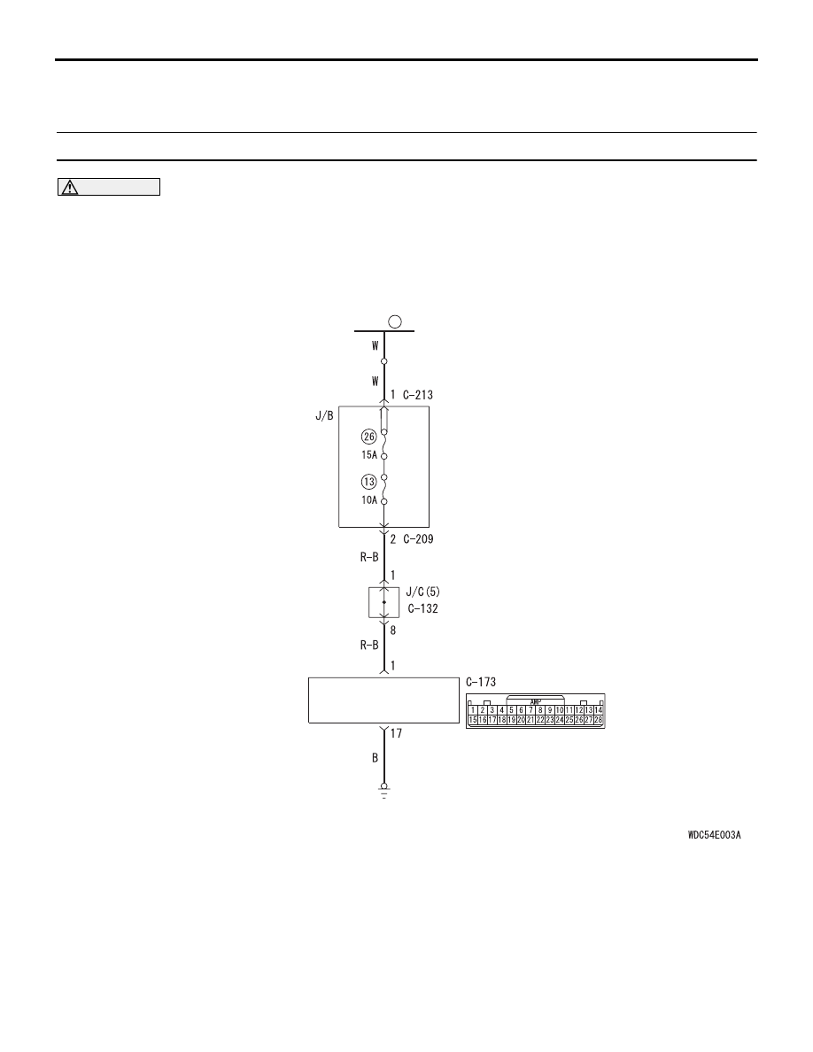
Inspection Procedure 1: Check the hands free ECU power supply circuit.

CAUTION

Before replacing the ECU, ensure that the power 
supply circuit, the earth circuit and the communi-
cation circuit are normal.

Hands-Free ECU Power Source Circuit

Wire colour code 
B : Black     LG : Light green     G : Green     L : Blue     W : White     Y : Yellow     SB : Sky blue 
BR : Brown     O : Orange     GR : Grey     R : Red     P : Pink     V : Violet     PU : Purple     SI : Silver

FUSIBLE 
LINK

20

HANDS-FREE ECU

HANDS FREE-ECU

CHASSIS ELECTRICAL

54A-412

CIRCUIT OPERATION

• The power supply to the hands free ECU is pro-

vided by the fusible link (20).

• The ACC signal is received from C-126 radio and 

CD player connector terminal No.28. <Vehicles 
with radio and CD player>

• The ACC signal is received from C-168 multivi-

sion display connector terminal No.72. <Vehicles 
with MMCS>

PROBABLE CAUSES

• Damaged harness wires and connectors

• Malfunction of the hands free ECU

• Malfunction of the radio and CD player <Vehicles 

with radio and CD player>

• Malfunction of the MMCS <Vehicles with MMCS>

DIAGNOSIS PROCEDURE

STEP 1. Connector check: C-173 hands free ECU 
connector

Q: Is the check result normal?

YES : 

Go to Step 2.

NO : 

Repair the defective connector.

STEP 2. Resistance measurement at C-173 hands 
free ECU connector.
(1) Disconnect the connector, and measure at the 

wiring harness side.

(2) Check the continuity between terminal 17 and 

earth.

OK: Continuity exists (2 

 or less)

Q: Is the check result normal?

YES : 

Go to Step 4.

NO : 

Go to Step 3.

STEP 3. Check the wiring harness between C-173 
hands free ECU connector terminal No.17 and 
body earth.

• Check the body earth wires for open circuit.

Q: Is the check result normal?

YES : 

The trouble can be an intermittent 

malfunction (Refer to GROUP 00 

− How to 

use Troubleshooting/inspection Service 
Points 

− How to Cope with Intermittent 

Malfunction ).

NO : 

Repair the wiring harness.

STEP 4. Voltage measurement at C-173 hands 
free ECU connector.
(1) Disconnect the connector, and measure at the 

wiring harness side.

(2) Measure the voltage between terminal No.1 and 

body earth.

OK: System voltage

Q: Is the check result normal?

YES : 

Go to Step 6.

NO : 

Go to Step 5.

Wire colour code 
B : Black     LG : Light green     G : Green     L : Blue     W : White     Y : Yellow     SB : Sky blue 
BR : Brown     O : Orange     GR : Grey     R : Red     P : Pink     V : Violet     PU : Purple     SI : Silver

Hands-Free ECU Communication Circuit

VEHICLES WITH MMCS

:

VEHICLES WITH RADIO AND CD PLAYER

:

NOTE

HANDS-FREE ECU

RADIO AND CD PLAYER 
OR 
MULTIVISION DISPLAY

HANDS FREE-ECU

CHASSIS ELECTRICAL

54A-413

STEP 5. Check the wiring harness between C-173 
hands free ECU connector terminal No.1 and 
fusible link (20).

• Check the power supply line for open circuit and 

short circuit.

NOTE: Prior to the wiring harness inspection, check 
junction block connectors C-209, C-213 and joint 
connector C-132, and repair if necessary.

Q: Is the check result normal?

YES : 

The trouble can be an intermittent 

malfunction (Refer to GROUP 00 

− How to 

use Troubleshooting/inspection Service 
Points 

− How to Cope with Intermittent 

Malfunction ).

NO : 

Repair the wiring harness.

STEP 6. Voltage measurement at C-173 hands 
free ECU connector.
(1) Disconnect the connector, and measure at the 

wiring harness side.

(2) Turn the ignition switch to "ACC" position.
(3) Measure the voltage between terminal No.15 and 

body earth.

OK: System voltage

Q: Is the check result normal?

YES : 

Replace the hands free ECU.

NO : 

Go to Step 7.

STEP 7. Connector check: C-126 radio and CD 
player connector <vehicles with radio and CD 
player> or C-168 multivision display connector 
<vehicles with MMCS>

Q: Is the check result normal?

YES : 

Go to Step 8.

NO : 

Repair the defective connector.

STEP 8. Check the harness wire between C-126 
radio and CD player connector terminal No.28 
<vehicles with radio and CD player> or C-168 
multivision display connector terminal No.72 
<vehicles with MMCS> and C-173 hands free ECU 
connector terminal No.15.

• Check the signal line for open circuit and short 

circuit.

Q: Is the check result normal?

YES : 

Replace the radio and CD player <vehicles 

with radio and CD player> or multivision 
display <vehicles with MMCS>.

NO : 

Repair the wiring harness.

HANDS FREE-ECU

CHASSIS ELECTRICAL

54A-414

Inspection Procedure 2: The USB memory device data cannot be replayed. <Vehicles with radio and 
CD player>

CAUTION

Before replacing the hands free ECU, ensure that the power supply circuit, the earth circuit and the 
communication circuit are normal.

COMMENTS ON TROUBLE SYMPTOM
If the sound replay is impossible with the USB mode, 
USB cable, hands free ECU, or radio and CD player 
may be defective, or a communication error between 
the radio and CD player and the hands free ECU 
may have occurred.
NOTE: Before troubleshooting, check that the music 
file (the customer tried to replay) can be replayed.

PROBABLE CAUSES

• The radio and CD player may be defective.

• The hands free ECU may be defective.

• The USB cable may be defective.

• Damaged harness wires and connectors

DIAGNOSIS PROCEDURE

STEP 1. Check the radio and CD player 
operation.
Check if the radio and CD player work normally and 
the sound is output.

Q: Is the check result normal?

YES : 

Go to Step 2.

NO : 

Troubleshoot the radio and CD player. Refer 
to 

P.54A-232

.

STEP 2. Check the diagnosis mode
Check if the hands free ECU can be switched to the 
diagnosis mode. (Refer to 

P.54A-403

.)

Q: Is the check result normal?

YES : 

Go to Step 3.

NO : 

Perform Inspection Procedure 5 
"DIAGNOSIS MODE cannot be made an 
entry." (Refer to 

P.54A-421

.)

STEP 3. Check the USB cable.
Check that the USB cable is connected to the hands 
free ECU normally. Or check the USB cable for dam-
age such as bend.

Q: Is the check result normal?

YES : 

Go to Step 4.

NO : 

Replace or repair the USB cable.

Wire colour code 
B : Black     LG : Light green     G : Green     L : Blue     W : White     Y : Yellow     SB : Sky blue 
BR : Brown     O : Orange     GR : Grey     R : Red     P : Pink     V : Violet     PU : Purple     SI : Silver

Hands-Free ECU Communication Circuit

HANDS-FREE ECU

USB 
CONNECTOR

RADIO AND CD PLAYER

USB CABLE


Content   ..  759  760  761  762   ..