Mitsubishi L200. Manual - part 706


  Index      Mitsubishi     Mitsubishi L200 - service repair manual 2012 year


Search            


Content   ..  704  705  706  707   ..


Mitsubishi L200. Manual - part 706


INTERIOR LAMP

CHASSIS ELECTRICAL

54A-191

NOTE: 

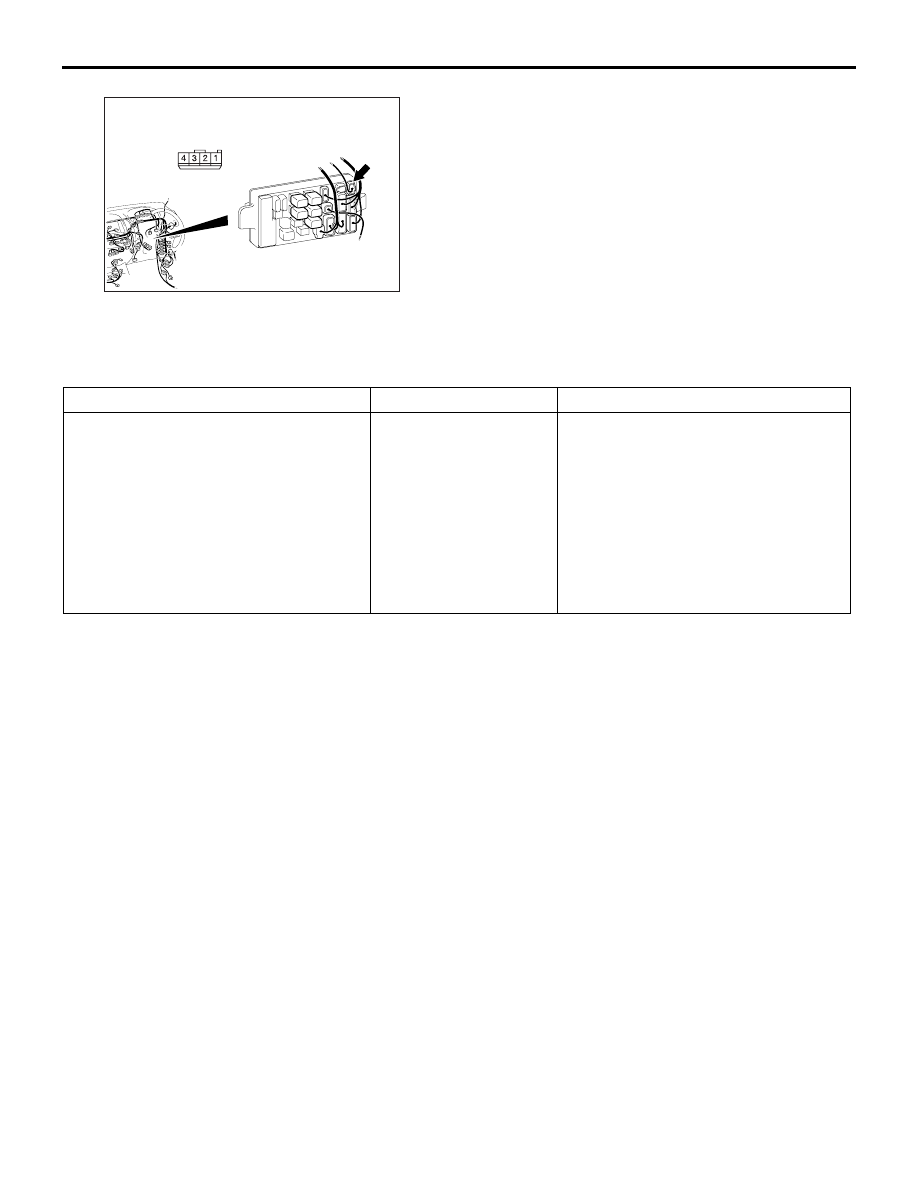
Prior to the wiring harness inspection, check junction 
block connector C-206, and repair if necessary.
Check the input and output lines for open circuit.

Q: Is the check result normal?

YES : 

The trouble can be an intermittent 

malfunction (Refer to GROUP 00 

− How to 

Cope with Intermittent Malfunction ).

NO : 

Repair the wiring harness.

ON-VEHICLE SERVICE

CUSTOMISATION FUNCTION

M1541301200035

The following functions can be customised using 
M.U.T.-III.

REMOVAL AND INSTALLATION

M1541301000031

For the front room lamp assembly and the rear room 
lamp refer to GROUP 52A, Headlining 

− Removal 

and installation .

AC509936

Connector: C-206 <RHD>

Harness side

BA

Junction block 
(Front view)

Function

Item name

Configuration

Room lamp delay-off time

Room lamp delay timer 
with door

• 0 s

• 7.5 s (initial condition <vehicles 

without central door locking 
system>)

• 15 s (initial condition <vehicles with 

central door locking system>)

• 30 s

• 60 s

• 120 s

• 180 s

REAR COMBINATION LAMP

CHASSIS ELECTRICAL

54A-192

REAR COMBINATION LAMP

SPECIAL TOOLS

M1541400100021

REAR COMBINATION LAMP

CHASSIS ELECTRICAL

54A-193

Tool

Number

Name

Use

MB990784

Ornament 
remover

Removal of rear combination lamp 
assembly

MB990784

REAR COMBINATION LAMP

CHASSIS ELECTRICAL

54A-194

MB991955

a. MB991824
b. MB991827
c. MB991910
d. MB991911
e. MB991825
f. MB991826

M.U.T.-III sub-
assembly

a. Vehicle 

Communicatio
n Interface 
(V.C.I.)

b. M.U.T.-III USB 

cable

c. M.U.T.-III main 

harness A 
(Vehicles with 
CAN 
communication 
system)

d. M.U.T.-III main 

harness B 
(Vehicles 
without CAN 
communication 
system)

e. M.U.T.-III 

measure 
adapter

f. M.U.T.-III 

trigger harness

CAUTION

For vehicles with CAN 
communication, use M.U.T.-III 
main harness A to send simulated 
vehicle speed. If you connect 
M.U.T.-III main harness B instead, 
the CAN communication does not 
function correctly.
Diagnosis code, service data and 
actuator test check.

MB991223

a. MB991219
b. MB991220
c. MB991221
d. MB991222

Harness set

a. Check harness
b. LED harness
c. LED harness 

adapter

d. Probe

Continuity check and voltage 
measurement at harness wire or 
connector

a. For checking connector pin 

contact pressure

b. For checking power supply circuit
c. For checking power supply circuit
d. For connecting a locally sourced 

tester

Tool

Number

Name

Use

MB991910

MB991826

MB991955

MB991911

MB991824

MB991827

MB991825

a

b

c

d

e

f

DO NOT USE

MB991223

a

d

c

b

DO NOT USE

BA


Content   ..  704  705  706  707   ..