Mitsubishi L200. Manual - part 673


  Index      Mitsubishi     Mitsubishi L200 - service repair manual 2012 year


Search            


Content   ..  671  672  673  674   ..


Mitsubishi L200. Manual - part 673


COMBINATION METER

CHASSIS ELECTRICAL

54A-59

tool test harness (MB991219) between the wiring 
harness connector terminals 1 and 2.

(3) Turn the ignition switch to the "ON" position.

Q: Does the test lamp illuminate?

YES : 

Go to Step 7.

NO : 

Go to Step 2.

STEP 2. Connector check: Combination meter 
connector C-113 and fuel gauge unit connector 
F-09.

Q: Is combination meter connector C-113 and fuel 

gauge unit connector F-09 in good condition?
YES : 

Go to Step 3.

NO : 

Repair or replace the damaged 
component(s). 

STEP 3. Check the wiring harness between 
combination meter connector C-113 (terminal 22) 
and fuel gauge unit connector F-09 (terminal 1).
Check the input lines for open circuit and short cir-
cuit.

NOTE: 

Prior to the wiring harness inspection, check interme-
diate connector C-30 and repair if necessary.

Q: Is the wiring harness between combination meter 

connector C-113 (terminal 22) and fuel gauge unit 
connector F-09 (terminal 1) in good condition?
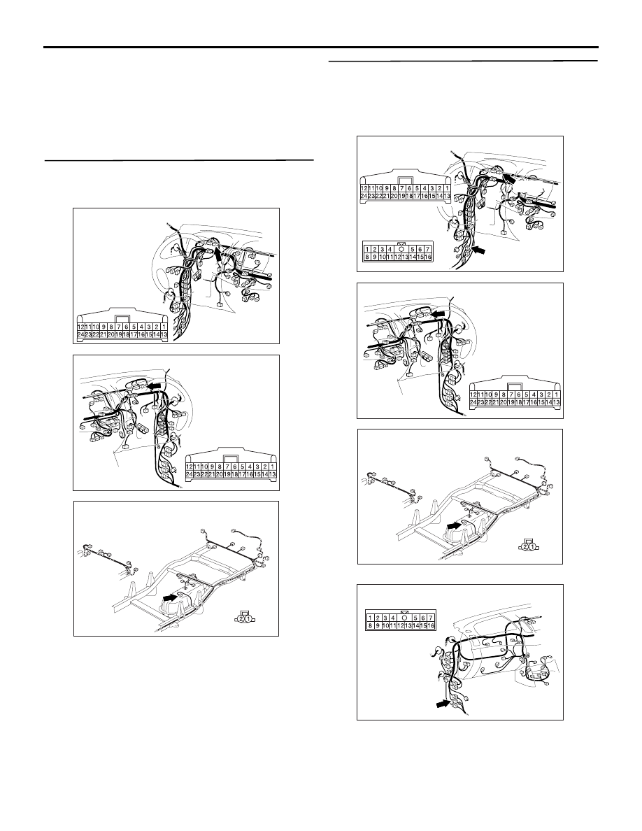
AC903856

Harness side 

BH

Connector: C-113 <LHD>

AC903868

Harness side 

BY

Connector: C-113 <RHD>

AC903957AB

Connector: F-09

Harness side

<Vehicles without 
rear body>

AC903856

Connectors: C-30, C-113 <LHD>

BJ

C-30

C-30

C-113

Harness side 

C-113

AC903868

Harness side 

BY

Connector: C-113 <RHD>

AC903957AB

Connector: F-09

Harness side

<Vehicles without 
rear body>

AC903865

Connector: C-30 <RHD>

AN

COMBINATION METER

CHASSIS ELECTRICAL

54A-60

YES : 

Go to Step 4.

NO : 

Repair or replace the damaged 
component(s). Then go to Step 4.

STEP 4. Retest the system.

Q: Is the fuel gauge normal?

YES : 

The procedure is complete. (If no 

malfunctions are found in all steps, an 
intermittent malfunction is suspected. Refer 
to GROUP 00 / How to Cope with 
Intermittent Malfunction ).

NO : 

Go to Step 5.

STEP 5. Check the wiring harness between fuel 
gauge unit connector F-09 (terminal 2) and earth.
Check the earth wires for open circuit.

Q: Is the wiring harness between fuel gauge unit 

connector F-09 (terminal 2) and earth in good 
condition?

YES : 

Go to Step 6.

NO : 

Repair or replace the damaged 
component(s).

STEP 6. Retest the system.

Q: Is the fuel gauge normal?

YES : 

The procedure is complete. (If no 

malfunctions are found in all steps, an 
intermittent malfunction is suspected. Refer 
to GROUP 00 / How to Cope with 
Intermittent Malfunction ).

NO : 

Carry out the troubleshooting again.

STEP 7. Check the fuel gauge unit.
Refer to 

P.54A-88

.

Q: Is the fuel gauge normal?

YES : 

Go to Step 8.

NO : 

Replace the fuel gauge unit.

STEP 8. Retest the system.

Q: Is the fuel gauge normal?

YES : 

The procedure is complete. (If no 

malfunctions are found in all steps, an 
intermittent malfunction is suspected. Refer 
to GROUP 00 / How to Cope with 
Intermittent Malfunction ).

NO : 

Replace combination meter. 

AC903957AB

Connector: F-09

Harness side

<Vehicles without 
rear body>

COMBINATION METER

CHASSIS ELECTRICAL

54A-61

Inspection Procedure 8: Engine coolant temperature gauge does not work (Other meters work).

COMMENTS ON TROUBLE SYMPTOM
If only the engine coolant temperature gauge does 
not operate, the engine ECU system, the combina-
tion meter, the wiring harness or its connector may 
be defective.

PROBABLE CAUSES

• Damaged harness wires and connectors

• Malfunction of the engine coolant temperature 

gauge unit

• Malfunction of combination meter

DIAGNOSIS PROCEDURE

STEP 1. Check the engine coolant temperature 
gauge circuit.

(1) Disconnect the A-108 engine coolant 

temperature gauge unit connector.

(2) Connect a test lamp (12 V 

− 3.4 W to 12 V − 7.0 

W) to the wiring harness side connector.

(3) Ignition switch: ON

Q: Does the test lamp illuminate?

YES : 

Go to Step 5.

NO : 

Go to Step 2.

Engine Coolant Temperature Gauge Circuit

ENGINE COOLANT 
TEMPERATURE 
GAUGE UNIT

COMBINATION 
METER

T/GA

Wire colour code 
B : Black     LG : Light green     G : Green     L : Blue     W : White     Y : Yellow     SB : Sky blue 
BR : Brown     O : Orange     GR : Grey     R : Red     P : Pink     V : Violet     PU : Purple     SI : Silver

NOTE

: LHD
: RHD

AC903898

AC

Connector: A-108

Harness side

A-108 (B)

AC503028AC

Connector

Earth

Test lamp
(12 V 3.4 W - 7.0 W)

Engine coolant 
temperature gauge unit

COMBINATION METER

CHASSIS ELECTRICAL

54A-62

STEP 2. Connector check: Combination meter 
connector C-113 and engine coolant temperature 
gauge unit connector A-108.

Q: Is combination meter connector C-113 and engine 

coolant temperature gauge unit connector A-108 in 
good condition?

YES : 

Go to Step 3.

NO : 

Repair or replace the damage 
component(s).

STEP 3. Retest the system.

Q: Is the engine coolant temperature gauge normal?

YES : 

The procedure is complete. (If no 

malfunctions are found in all steps, an 
intermittent malfunction is suspected. Refer 
to GROUP 00 / How to Cope with 
Intermittent Malfunction ).

NO : 

Go to Step 4.

AC903898

AC

Connector: A-108

Harness side

A-108 (B)

AC903856

Harness side 

BH

Connector: C-113 <LHD>

AC903868

Harness side 

BY

Connector: C-113 <RHD>


Content   ..  671  672  673  674   ..