Mitsubishi L200. Manual - part 637


  Index      Mitsubishi     Mitsubishi L200 - service repair manual 2012 year


Search            


Content   ..  635  636  637  638   ..


Mitsubishi L200. Manual - part 637


TROUBLESHOOTING

SUPPLEMENTAL RESTRAINT SYSTEM (SRS)

52B-219

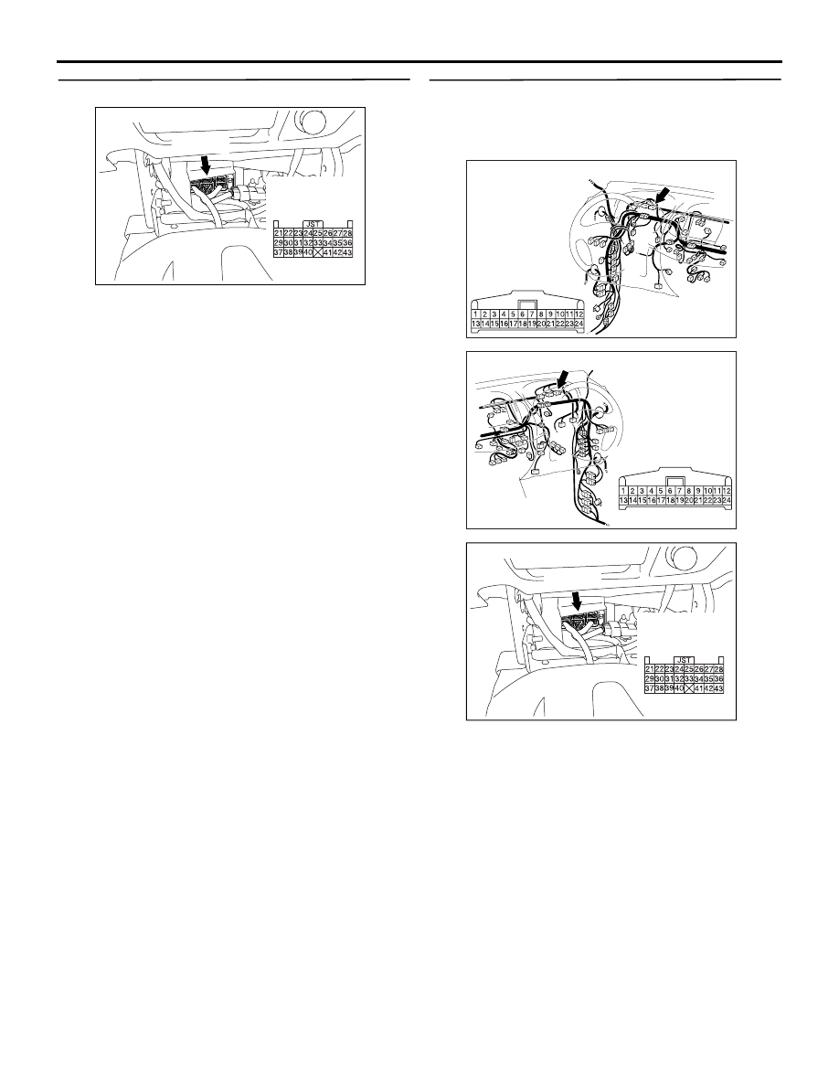
STEP 4. Check SRS-ECU connector C-154.

AC801404

AJ

Connector: C-154

C-154 (Y)

Harness side 
connector 
(rear view)

Q: Is the connector correctly engaged?

YES : 

Go to Step 5.

NO : 

Engage the connector correctly. Then go to 
Step 7.

STEP 5. Check the harness for short circuit 
between the combination meter connector C-113 
(terminal No.18) and SRS-ECU connector C-154 
(terminal No.39).

AC903856BM

Connector: C-113 <LHD>

Harness side 
connector 
(rear view)

AC903868

CC

Connector: C-113 <RHD>

Harness side 
connector 
(rear view)

AC801404

AJ

Connector: C-154

C-154 (Y)

Harness side 
connector 
(rear view)

Q: Is the check result normal?

YES : 

Go to Step 6.

NO : 

Repair the harness wires between the 
combination meter connector C-113 
(terminal No.18) and SRS-ECU connector 
C-154 (terminal No.39). Then go to Step 7

TROUBLESHOOTING

SUPPLEMENTAL RESTRAINT SYSTEM (SRS)

52B-220

STEP 6. Check the SRS warning lamp.
(1) Disconnect the negative battery terminal.

AC801404

AJ

Connector: C-154

C-154 (Y)

Harness side 
connector 
(rear view)

(2) Disconnected the SRS-ECU connector C-154.
(3) Connect the negative battery terminal.
(4) Turn the ignition switch to the "ON" position.

Q: Does the SRS warning lamp illuminate?

YES : 

Go to Step 7.

NO : 

Replace the combination meter (Refer to 
GROUP 54A, Combination Meter Assembly 
). Go to Step 7. 

STEP 7. Check whether the diagnosis code is 
reset.
Check again if the diagnosis code is set.
(1) Erase the diagnosis code.
(2) Ignition: "LOCK" (OFF) position to "ON"
(3) On completion, check that the diagnosis code is 

not reset.

Q: Is the diagnosis code set?

YES : 

Replace the SRS-ECU (Refer to 

P.52B-

266

).

NO : 

An intermittent malfunction is suspected 
(Refer to GROUP 00, How to Cope with 
Intermittent Malfunction ).

TROUBLESHOOTING

SUPPLEMENTAL RESTRAINT SYSTEM (SRS)

52B-221

Code No.B1551: SRS warning lamp circuit malfunction (Lamp does not Switch Off).

AC801181

Wire colour code
B : Black     LG : Light green     G : Green     L : Blue     W : White     Y : Yellow     SB : Sky blue
BR : Brown     O : Orange     GR : Grey     R : Red     P : Pink     V : Violet     PU : Purple

SRS Warning Lamp Drive Circuit

IGNITION
SWITCH (IG1)

COMBINATION
METER

SRS-ECU

AD

OPERATION

• Power for the SRS warning lamp is supplied from 

the ignition switch (IG1) circuit.

• The SRS warning lamp illuminates when the igni-

tion switch is turned to the "ON" position and 
goes out after approximately 7 seconds if there is 
not a malfunction in the SRS system.

DIAGNOSIS CODE SET CONDITIONS

• This diagnosis code will be set if an open circuit 

has occurred in the wiring harness between the 
combination meter and the SRS-ECU.

TROUBLESHOOTING HINTS

• Damaged wiring harnesses of connectors

• Malfunction of the SRS-ECU

• Malfunction of the combination meter

TROUBLESHOOTING

SUPPLEMENTAL RESTRAINT SYSTEM (SRS)

52B-222

DIAGNOSIS PROCEDURE

STEP 1. M.U.T.-III diagnosis code.

Q: Is the diagnosis code set?

YES : 

Perform the troubleshooting to the set 

diagnosis code. (Refer to 

P.52B-12

).

NO : 

Go to Step 2.

STEP 2. Check the harness between SRS-ECU 
connector C-154 (terminal No.39) and the 
combination meter connector C-113 (terminal 
No.18).

AC903856BM

Connector: C-113 <LHD>

Harness side 
connector 
(rear view)

AC903868

CC

Connector: C-113 <RHD>

Harness side 
connector 
(rear view)

AC801404

AJ

Connector: C-154

C-154 (Y)

Harness side 
connector 
(rear view)

• Check the SRS warning lamp output lines for 

open circuit.

Q: Is the check result normal?

YES : 

Go to Step 3.

NO : 

Repair the harness wires. Then go to Step 
4.

STEP 3. Check the SRS warning lamp.
(1) Disconnect the negative battery terminal.

AC801404

AJ

Connector: C-154

C-154 (Y)

Harness side 
connector 
(rear view)

(2) Disconnected the SRS-ECU connector C-154.
(3) Connect the negative battery terminal.
(4) Turn the ignition switch to the "ON" position.

CAUTION

Do not insert a test probe into the terminal from 
its front side directly, as the connector contact 
pressure may be weakened.
(5) Check that SRS warning lamp turn "ON" when 

SRS-ECU connector C-154 is disconnected. 
Check that the same warning lamp turn "OFF" 
when the terminal No.39 of the above connector 
is earthed.

Q: Is the check result normal?

YES : 

Go to Step 4

NO : 

Replace the combination meter (Refer to 
GROUP 54A, Combination Meter Assembly 
). 

STEP 4. Check whether the diagnosis code is 
reset.
Check again if the diagnosis code is set.
(1) Erase the diagnosis code.
(2) Ignition: "LOCK" (OFF) position to "ON"
(3) On completion, check that the diagnosis code is 

not reset.

Q: Is the diagnosis code set?

YES : 

Replace the SRS-ECU (Refer to 

P.52B-

266

).

NO : 

An intermittent malfunction is suspected 
(Refer to GROUP 00, How to Cope with 
Intermittent Malfunction ).


Content   ..  635  636  637  638   ..