Mitsubishi L200. Manual - part 614
TROUBLESHOOTING
SUPPLEMENTAL RESTRAINT SYSTEM (SRS)
52B-127
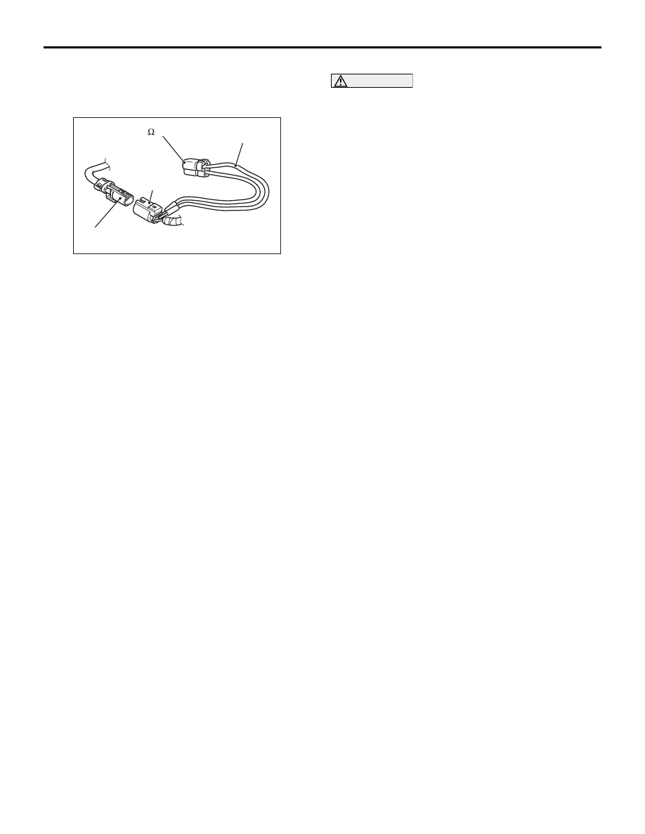
D-36. When disconnecting connector D-36,
unlock the connector by sliding the locking button
to the direction of the arrow as shown in the
figure, and then disconnect the connector.
AC507310 BG
D-36
Side-airbag
module (RH) connector
D-36
Harness side
connector
MB991865
(Dummy resistor: 3 )
MB991866
(Resistor harness)
(3) Connect special tool dummy resistor (MB991865)
to special tool resistor harness (MB991866).
CAUTION
Do not insert a test probe into the terminal from
its front side directly as the connector contact
pressure may be weakened.
(4) Insert special tool (MB991866) into the harness
side connector D-36 by backprobing.
(5) Connect the negative battery terminal.
(6) Erase the diagnosis code memory, and check the
diagnosis code.
Q: Is diagnosis code B1420 set?
YES :
Go to Step 5
NO :
Replace the front seatback assembly (RH)
(Refer to
).