Mitsubishi L200. Manual - part 610
TROUBLESHOOTING
SUPPLEMENTAL RESTRAINT SYSTEM (SRS)
52B-111
STEP 5. Check the diagnosis code by connecting
a dummy resistor. (M.U.T.-III diagnosis code)
(1) Disconnect the negative battery terminal.
AC509788
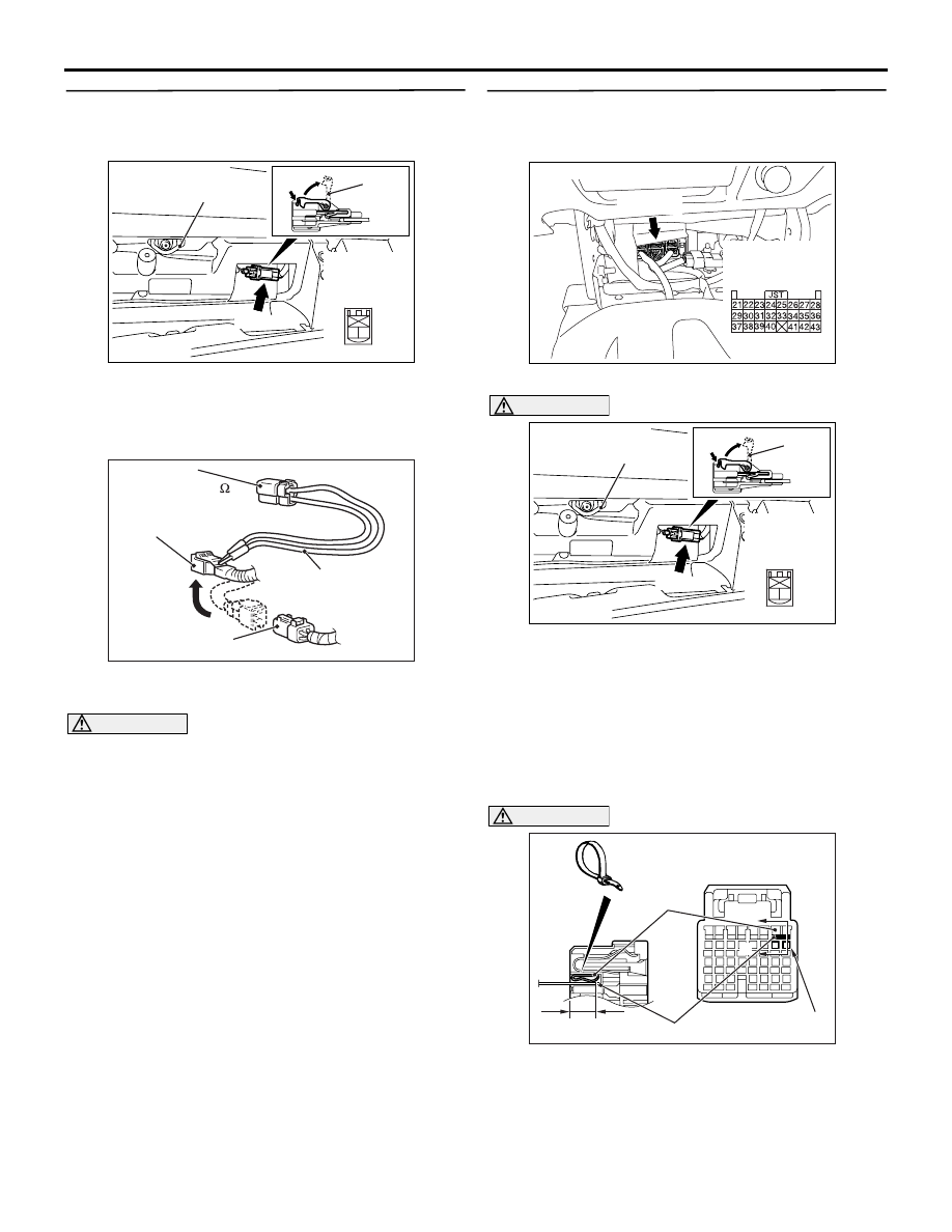
C-02 (R)
AC
Glove box striker
2 1
Harness side
connector
(front view)
Lock
lever
Connector: C-02
(2) Disconnect passenger’s (front) air bag module
connector C-02. Pull up the harness side lock
lever with a nail and disconnect the connector
lock.
AC300956 AP
MB991865
(Dummy resistor: 3 )
MB991866
(Resistor harness)
C-02 Passenger's
(front) air bag
module connector
C-02 Harness side
connector
(3) Connect special tool dummy resistor (MB991865)
to special tool resistor harness (MB991866).
CAUTION
Do not insert a test probe into the terminal from
its front side directly as the connector contact
pressure may be weakened.
(4) Insert special tool (MB991866) into the harness
side connector C-02 by backprobing.
(5) Check that the passenger's air bag cut off switch
is "ON" position.
(6) Connect the negative battery terminal.
(7) Erase the diagnosis code memory, and check the
diagnosis code.
Q: Is diagnosis code B1410 set?
YES :
Go to Step 6.
NO :
Replace the passenger's (front) air bag
module (Refer to
STEP 6. Resistance measurement at SRS-ECU
connector C-154.
(1) Disconnect the negative battery terminal.
AC801404
AJ
Connector: C-154
C-154 (Y)
Harness side
connector
(rear view)
(2) Disconnect SRS-ECU connector C-154.
AC509788
C-02 (R)
AC
Glove box striker
2 1
Harness side
connector
(front view)
Lock
lever
Connector: C-02
DANGER
To prevents the air bag from deploying unin-
tentionally, disconnect the passenger’s
(front) air bag module connector C-02 to
short the squib circuit.
(3) Disconnect passenger’s (front) air bag module
connector C-02. Pull up the harness side lock
lever with a nail and disconnect the connector
lock.
AC801565
Section
A - A
C-154 Harness side connectors
(front view)
Cable tie
Terminal
7 mm or more
AE
Short spring
A
A
CAUTION
Insert an insulator such as a cable tie to a depth
of 7 mm or more, otherwise the short spring will
not be released.
(4) Insert a cable tie [3 mm wide, 0.5 mm thick]
between terminals 21, 22 and the short spring to
release the short spring.