Mitsubishi L200. Manual - part 598


  Index      Mitsubishi     Mitsubishi L200 - service repair manual 2012 year


Search            


Content   ..  596  597  598  599   ..


Mitsubishi L200. Manual - part 598


TROUBLESHOOTING

SUPPLEMENTAL RESTRAINT SYSTEM (SRS)

52B-63

DIAGNOSIS PROCEDURE

STEP 1. M.U.T.-III diagnosis code.

Q: Is the diagnosis code set?

YES : 

Perform the troubleshooting to the set 

diagnosis code. (Refer to 

P.52B-12

).

NO : 

Go to Step 2.

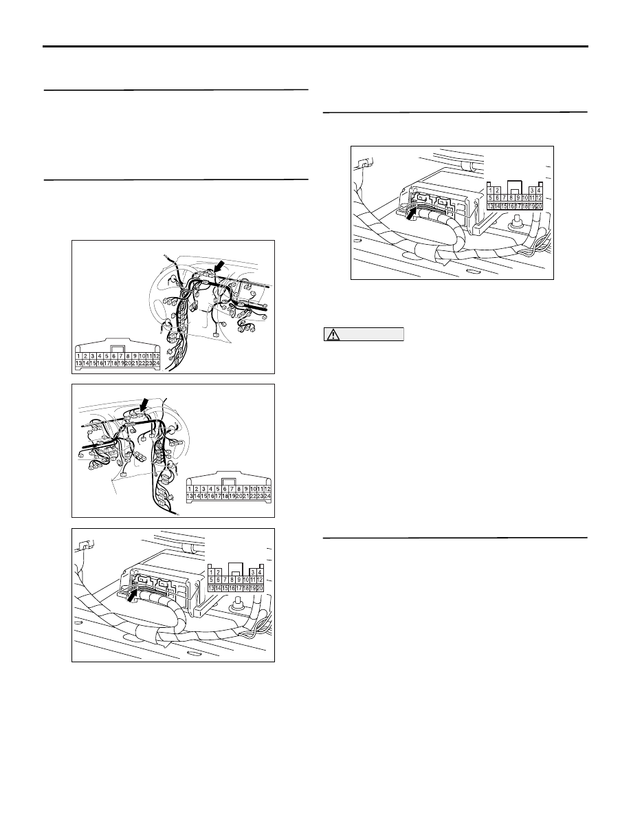
STEP 2. Check the harness between SRS-ECU 
connector C-131 (terminal No.8) and the 
combination meter connector C-113 (terminal 
No.18).

AC903856BM

Connector: C-113 <LHD>

Harness side 
connector 
(rear view)

AC903868

CC

Connector: C-113 <RHD>

Harness side 
connector 
(rear view)

AC501670

AB

C-131 (Y)

Connector: C-131

Harness side 
connector 
(rear view)

• Check the SRS warning lamp output lines for 

open circuit.

Q: Is the check result normal?

YES : 

Go to Step 3.

NO : 

Repair the harness wires. Then go to Step 
4.

STEP 3. Check the SRS warning lamp.
(1) Disconnect the negative battery terminal.

AC501670

AB

C-131 (Y)

Connector: C-131

Harness side 
connector 
(rear view)

(2) Disconnected the SRS-ECU connector C-131.
(3) Connect the negative battery terminal.
(4) Turn the ignition switch to the "ON" position.

CAUTION

Do not insert a test probe into the terminal from 
its front side directly, as the connector contact 
pressure may be weakened.
(5) Check that SRS warning lamp turn "ON" when 

SRS-ECU connector C-131 is disconnected. 
Check that the same warning lamp turn "OFF" 
when the terminal No.8 of the above connector is 
earthed.

Q: Is the check result normal?

YES : 

Go to Step 4

NO : 

Replace the combination meter (Refer to 
GROUP 54A, Combination Meter Assembly 
). 

STEP 4. Check whether the diagnosis code is 
reset.
Check again if the diagnosis code is set.
(1) Erase the diagnosis code.
(2) Ignition: "LOCK" (OFF) position to "ON"
(3) On completion, check that the diagnosis code is 

not reset.

Q: Is the diagnosis code set?

YES : 

Replace the SRS-ECU (Refer to 

P.52B-

266

).

NO : 

An intermittent malfunction is suspected 
(Refer to GROUP 00, How to Cope with 
Intermittent Malfunction ).

TROUBLESHOOTING

SUPPLEMENTAL RESTRAINT SYSTEM (SRS)

52B-64

Code No.B1595: Front impact sensor RH system (short circuit in the sensor)


Code No.B1596: Front impact sensor RH system (open circuit in the sensor)


Code No.B1597: Front impact sensor RH (short circuited in the earth)


Code No.B1598: Front impact sensor RH (short circuited in the power supply)


Code No.B1599: Front impact sensor LH system (short circuit in the sensor)


Code No.B1600: Front impact sensor LH  (open circuit in the sensor)


Code No.B1601: Front impact sensor LH (short circuited in the earth)


Code No.B1602: Front impact sensor LH (short circuited in the power supply)

AC900561

Front Impact Sensor Circuit

SRS-ECU

FRONT IMPACT
SENSOR (RH)

FRONT IMPACT
SENSOR (LH)

Wire colour code
B : Black     LG : Light green     G : Green     L : Blue     W : White     Y : Yellow     SB : Sky blue
BR : Brown     O : Orange     GR : Grey     R : Red     P : Pink     V : Violet     PU : Purple

AC

NOTE

: RHD

: LHD

OPERATION

• When the left and right front impact sensors 

detect a collision, the switches inside the sensors 
turn ON. 

• SRS-ECU judges how severe a collision is by 

detecting signals from the front impact sensors 
and the front air bag analogue G-sensor. If the 
impact is over a predetermined level, the SRS-
ECU sends an ignition signal. At this time, if the 
front air bag safing G-sensor is on, the SRS air 
bag will inflate. 

DIAGNOSIS CODE SET CONDITIONS
These diagnosis codes are set if these are abnormal 
resistance between the input terminals of the front 
impact sensors.
The most likely causes for these codes to be set are 
shown in the table below:

Code No.

Trouble causes

B1595

Right front impact sensor or its wiring shorted

B1596

Right front impact sensor or wiring open circuit

B1597

Short to body earth in the right front impact sensor harness

B1598

Short to the power supply in the right front impact sensor harness

B1599

Left front impact sensor or its wiring shorted

TROUBLESHOOTING

SUPPLEMENTAL RESTRAINT SYSTEM (SRS)

52B-65

PROBABLE CAUSES

• Damaged harness wires and connectors

• Front impact sensor failed

• Malfunction of the SRS-ECU

DIAGNOSIS PROCEDURE

STEP 1. Check the front impact sensor.
 Refer to 

P.52B-264

.

Q: Is the check result normal?

YES : 

Go to Step 2.

NO : 

Check the harness wires for open or short 
circuit between intermediate connector and 
front impact sensor, and repair if necessary. 
Then replace the front impact sensor (Refer 
to 

P.52B-263

).

STEP 2. Resistance measurement at the SRS-
ECU connector C-131.
(1) Disconnect the negative battery terminal.

AC501670

AB

C-131 (Y)

Connector: C-131

Harness side 
connector 
(rear view)

(2) Disconnect SRS-ECU connector C-131.

CAUTION

Do not insert a test probe into the terminal from 
its front side directly as the connector contact 
pressure may be weakened.

AC100338

AC103684

1314151617181920

5 6 7 8 9 101112

1 2

3 4

AC103683 AP

C-131 Harness side 
(rear view)
 

AC100338 

1314151617181920

5 6 7 8 9 101112

1 2

3 4

AC103684 AO

C-131 Harness side 
(rear view)
 

(3) Take the measurements below at harness side 

B1600

Left front impact sensor or wiring open circuit

B1601

Short to body earth in the left front impact sensor harness

B1602

Short to the power supply in the left front impact sensor harness

Code No.

Trouble causes

TROUBLESHOOTING

SUPPLEMENTAL RESTRAINT SYSTEM (SRS)

52B-66

connector C-131.

• Resistance between terminals 1 and 2 as well 

as 3 and 4.

OK: 820 

± 82 

AC103372

4

1

2

3

5

7

6

8

16

15

14

13

12

11

10

9

20

19

18

17

AM

C-131 Harness side 
(rear view)
 

• Continuity between terminals 1, 2, 3, 4 and 

body earth

OK: Open circuit

Q: Is the check result normal?

YES : 

Go to Step 3.

NO : 

 Repair the harness wire between the front 
impact sensor (RH) connector A-124 
(terminals 1 and 2) and SRS-ECU 
connector C-131 (terminals 1 and 2) as well 
as between front impact sensor (LH) 
connector A-30 (terminals 1 and 2) and 
SRS-ECU connector C-131 (terminals 4 and 
3).

STEP 3. Voltage measurement at the SRS-ECU 
connector C-131.
(1) Disconnect the negative battery terminal.

AC501670

AB

C-131 (Y)

Connector: C-131

Harness side 
connector 
(rear view)

(2) Disconnect SRS-ECU connector C-131.

(3) Connect the negative battery terminal.
(4) Turn the ignition switch to the "ON" position.

CAUTION

Do not insert a test probe into the terminal from 
its front side directly as the connector contact 
pressure may be weakened.

4

1

2

3

5

7

6

8

16

15

14

13

12

11

10

9

20

19

18

17

AC210613

C-131 Harness side 
(rear view)
 

AE

(5) Take the measurements below at harness-side 

connector C-131.

• Voltage between terminals 1, 2, 3, 4 and body 

earth

OK: 1 V or less

Q: Is the check result normal?

YES : 

Go to Step 4.

NO : 

 Repair the harness wire between the front 
impact sensor (RH) connector A-124 
(terminals 1 and 2) and SRS-ECU 
connector C-131 (terminals 1 and 2) as well 
as between front impact sensor (LH) 
connector A-30 (terminals 1 and 2) and 
SRS-ECU connector C-131 (terminals 4 and 
3).

STEP 4. Check whether the diagnosis code is 
reset.
Check again if the diagnosis code is set.

Q: Is diagnosis code B1595, B1596, B1597, B1598, 

B1599, B1600, B1601 or B1602 set?
YES : 

Replace the SRS-ECU (Refer to 

P.52B-

266

).

NO : 

An intermittent malfunction is suspected 
(Refer to GROUP 00, How to Cope with 
Intermittent Malfunction ).


Content   ..  596  597  598  599   ..