Mitsubishi L200. Manual - part 465
AC800980
AG
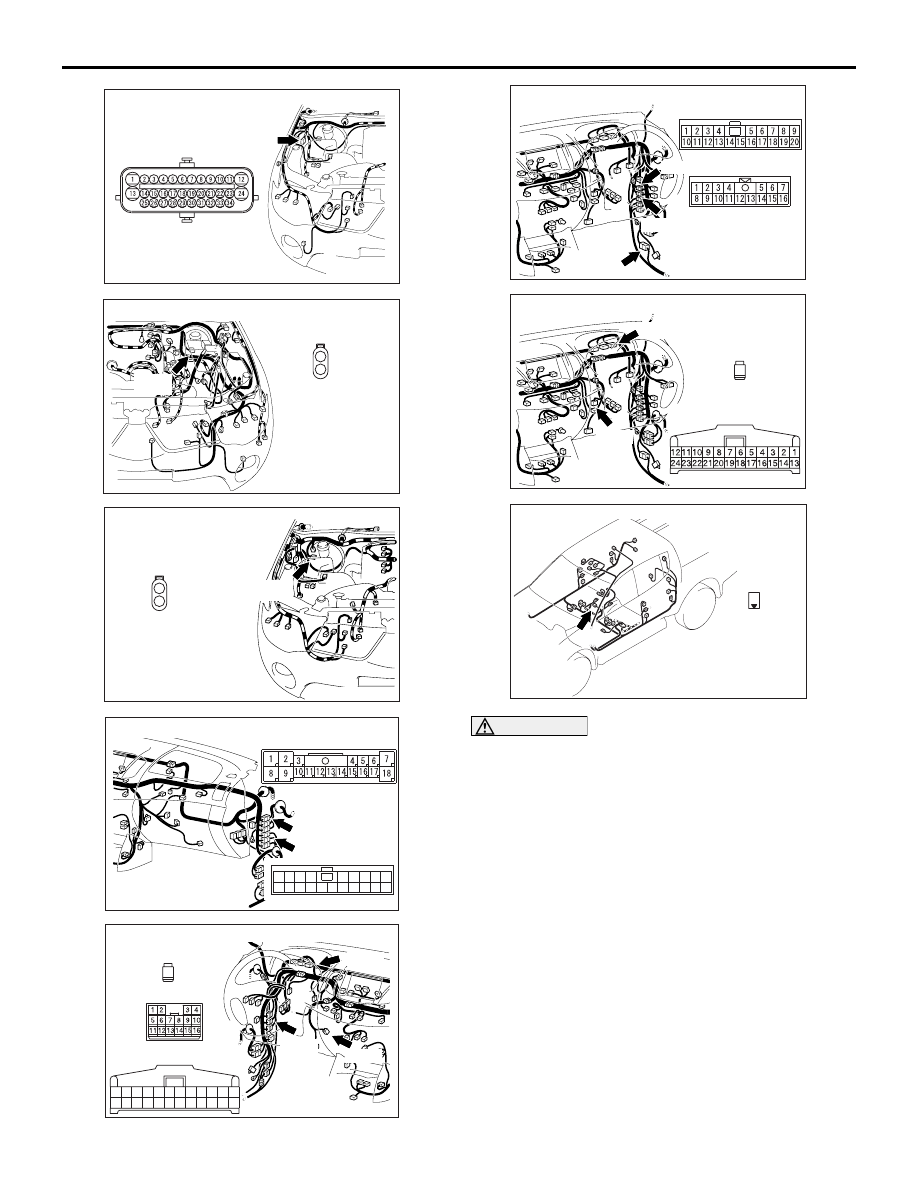
Connector: A-48
(B)
AC900745AB
Connector: A-102 <LHD>
(GR)
Harness connector
(harness side)
1
2
AC501971AS
Connector: A-102 <RHD>
Harness connector
(harness side)
1
2
(GR)
AC600688
Connector: C-13, C-59 <LHD>
BW
C-59
C-13
16
10
13
4
1112
1 2 3
15
14
5
20
18
17
19
7
6
8 9
C-59
C-13
AC600687CT
Connectors: C-47, C-54, C-113 <LHD>
C-54
C-54
C-47
C-113 Harness side
18
19
21
22
20
2423
11
12
10 9
7
8
6
1413
171615
3
4
5
1
2
C-113
1
C-47 Harness side
AC600623DI
Connector: C-13, C-14, C-59 <RHD>
C-13, C-59
C-14
C-59
C-14
C-13
AC600623DH
Connectors: C-47, C-113 <RHD>
Harness side
C-113
C-113
1
C-47 Harness side
C-47
AC509967AZ
Connector: D-19
Harness side
1
TROUBLESHOOTING
ACTIVE STABILITY & TRACTION CONTROL SYSTEM (ASTC)
35C-116
CAUTION
If there is any problem in the CAN bus lines, an
incorrect diagnosis code may be set. Diagnose
the CAN bus lines before the diagnosis codes
(Refer to GROUP 54C
− CAN Bus Diagnostics
Table .).
OPERATION
• ASTC-ECU send the illumination signal of Brake
warning lamp to the combination meter via the
CAN communication.
• ASTC-ECU operates the Brake warning lamp
and the Brake warning lamp for three seconds
after the ignition switch is turned "ON" position for
bulb check.
COMMENT
This may be caused by faults in the signal line, the
combination meter or the ASTC-ECU.
PROBABLE CAUSES
• Malfunction of the combination meter