Mitsubishi L200. Manual - part 461


  Index      Mitsubishi     Mitsubishi L200 - service repair manual 2012 year


Search            


Content   ..  459  460  461  462   ..


Mitsubishi L200. Manual - part 461


TROUBLESHOOTING

ACTIVE STABILITY & TRACTION CONTROL SYSTEM (ASTC)

35C-100

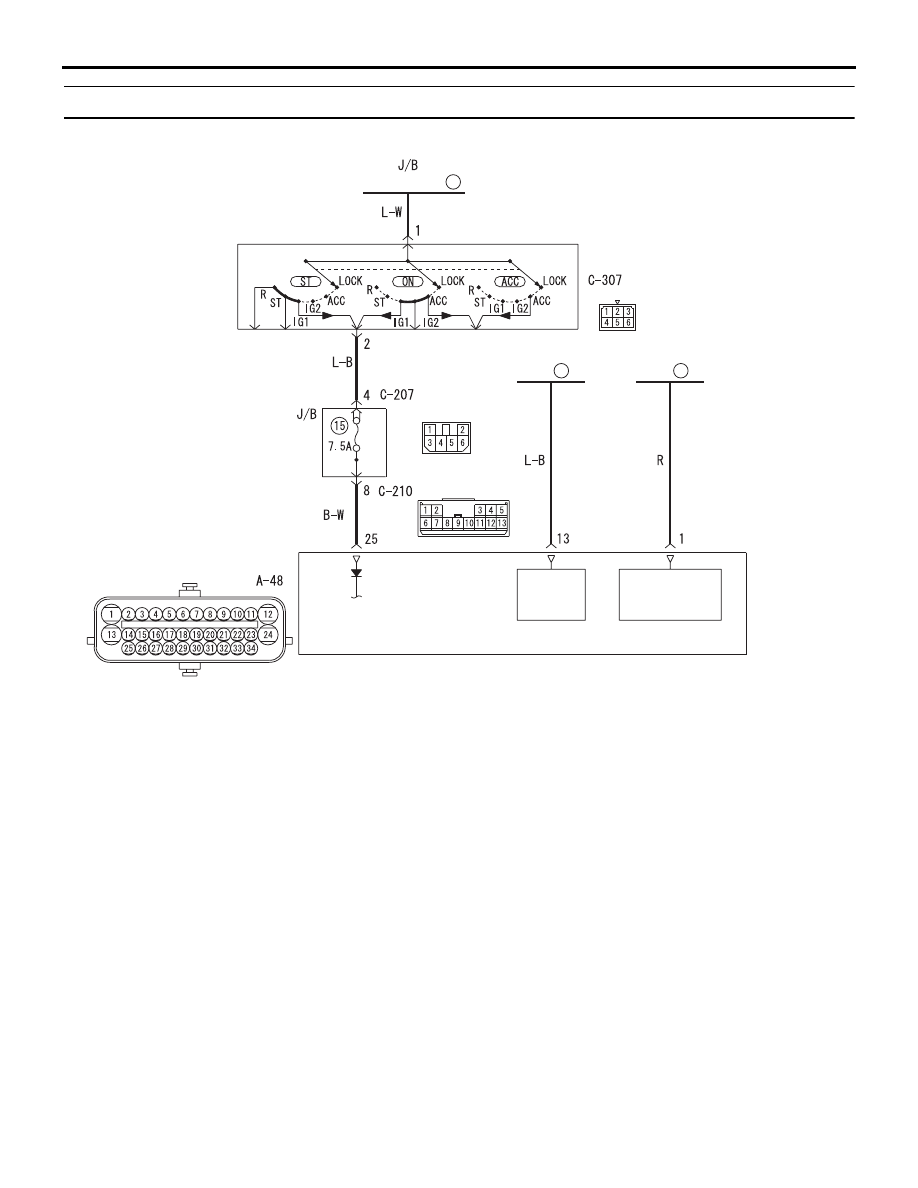
Code No.C1861: Low voltage at ASTC-ECU power supply

Wire colour code
B : Black     LG : Light green     G : Green     L : Blue     W : White     Y : Yellow     SB : Sky blue
BR : Brown     O : Orange     GR : Grey     R : Red     P : Pink     V : Violet     PU : Purple

ACB00777

(FUSIBLE LINK      )

3

IGNITION 
SWITCH

ASTC-ECU

MOTOR 
POWER 
SOURCE

SOLENOID 
VALVE POWER 
SOURCE

FUSIBLE 
LINK

21

FUSIBLE 
LINK

22

AC800980

AG

Connector: A-48

(B)

AC509934

Connectors: C-207, C-210 <LHD>

Junction block (Front view)

C-207

C-210

C-207

AO

Harness side

Harness side

C-210

AC509936

Connectors: C-207, C-210 <RHD>

C-207

C-210

C-207

Harness side

Harness side

C-210

AK

Junction block 
(Front view)

AC600048AI

Connector: C-307

Harness side

TROUBLESHOOTING

ACTIVE STABILITY & TRACTION CONTROL SYSTEM (ASTC)

35C-101

CAUTION

If there is any problem in the CAN bus lines, an 
incorrect diagnosis code may be set. Diagnose 
the CAN bus lines before the diagnosis codes 
(Refer to GROUP 54C 

 CAN Bus Diagnostics 

Table .).
OPERATION

• The ASTC-ECU is energized by the ignition 

switch (IG1) through multi-purpose fuse No.15 
and the ASTC-ECU terminal 25.

• Power supply for control solenoid valve and lin-

ear valve are supplied to the ASTC-ECU terminal 
1 via fusible link 21.

• Power supply for ABS motor is supplied to the 

ASTC-ECU terminal 13 via fusible link 22.

• The wheel speed sensors are energised via 

ASTC-ECU terminal No. 25.

DIAGNOSIS CODE SET CONDITION
This code is set if the supply power voltage drops 
abnormally.

PROBABLE CAUSES
The most likely causes for this diagnosis code to set 
are:

• Battery abnormality

• Charging system failed

• Damaged wiring harness or connector

• Malfunction of the hydraulic unit assembly (inte-

grated with ASTC-ECU)

• Battery terminal looseness

DIAGNOSIS PROCEDURE

STEP 1. M.U.T.-III CAN bus diagnosis
Use M.U.T.-III to diagnose the CAN bus lines.

Q: Is the check result normal?

YES : 

Go to Step 3.

NO : 

Repair the CAN bus lines (Refer to GROUP 
54C 

− CAN Bus Diagnostics Table .). On 

completion, go to Step 2.

STEP 2. Diagnosis code recheck after resetting 
CAN bus lines
(1) Erase the diagnosis code.
(2) Turn the ignition switch to the "LOCK" (OFF) 

position.

(3) Turn the ignition switch to the "ON" position.
(4) Check if the diagnosis code is set.

Q: Is the diagnosis code No.C1861 set?

YES : 

Go to Step 3.

NO : 

This diagnosis is complete.

STEP 3. Check the fusible link No.21, No.22 or 
the fuse No.15.
Visually check for open circuit in the fusible link 
No.21, No.22 or the fuse No.15.

Q: Is the check result normal?

YES : 

Go to Step 4.

NO : 

Replace the fusible link or fuse. Then go to 
Step 10.

TROUBLESHOOTING

ACTIVE STABILITY & TRACTION CONTROL SYSTEM (ASTC)

35C-102

STEP 4. Battery check
Refer to GROUP 54A 

− Battery Test .

Q: Is the battery in good condition?

YES : 

Go to Step 5.

NO : 

Charge or replace the battery. Then go to 
Step 10.

STEP 5. Charging system check
Refer to GROUP 16 

− Charging System .

Q: Is the charging system in good condition?

YES : 

Go to Step 6.

NO : 

Repair or replace the charging system 
component(s). Then go to Step 10.

STEP 6. Connector check: A-48 ASTC-ECU 
connector, C-207 junction block connector, C-210 
junction block connector, C-307 ignition switch 
(IG1) connector

Q: Is the check result normal?

YES : 

Go to Step 7.

NO  : 

Repair the damaged connector. Then go to 
Step 10.

STEP 7. Resistance measurement at A-48 ASTC-
ECU connector
(1) Disconnect the C-210 junction block connector.
(2) Disconnect the fusible link No.21 and No.22.
(3) Disconnect the A-48 ASTC-ECU connector, and 

measure at the wiring harness-side connector.

(4) Measure the resistance between the A-48 ASTC-

ECU connector terminal No.1, No.13, No.25 and 
the body earth.

OK: No continuity

Q: Is the check result normal?

YES : 

Go to Step 8.

NO : 

The short circuit may be present in the 
power supply circuit. Repair the wiring 
harness between the A-48 ASTC-ECU 
connector terminal No.1, No.13, No.25 and 
the fusible link No.21, No.22, the C-210 
junction block connector terminal No.8. 
Then go to Step 10.

STEP 8. Voltage measurement at A-48 ASTC-ECU 
connector
(1) Disconnect the A-48 ASTC-ECU connector.
(2) Turn the ignition switch to the "ON" position.
(3) Measure the resistance between the A-48 ASTC-

ECU connector terminal No.1, No.13, No.25 and 
the body earth.

OK: Battery voltage

Q: Is the check result normal?

YES : 

Go to Step 9.

NO : 

The open circuit may be present in the 
power supply circuit. Repair the wiring 
harness between the A-48 ASTC-ECU 
connector terminal No.1, No.13, No.25 and 
the fusible link No.21, No.22, the C-210 
junction block connector terminal No.8. 
Then go to Step 10.

STEP 9. Check whether the diagnosis code is 
reset.
(1) Erase the diagnosis code.
(2) Turn the ignition switch to the "LOCK" (OFF) 

position.

(3) Turn the ignition switch to the "ON" position.
(4) Check if the diagnosis code is set.

Q: Is the diagnosis code No. C1861 set?

YES : 

Replace the hydraulic unit (integrated with 

ASTC-ECU) (Refer to 

P.35C-140

.). Then go 

to Step 10.

NO : 

Intermittent malfunction (Refer to GROUP 
00 

− How to Cope with Intermittent 

Malfunctions .).

STEP 10. Check whether the diagnosis code is 
reset.
(1) Erase the diagnosis code.
(2) Turn the ignition switch to the "LOCK" (OFF) 

position.

(3) Turn the ignition switch to the "ON" position.
(4) Check if the diagnosis code is set.

Q: Is the diagnosis code No. C1861 set?

YES : 

Return to Step 1.

NO : 

This diagnosis is complete.

TROUBLESHOOTING

ACTIVE STABILITY & TRACTION CONTROL SYSTEM (ASTC)

35C-103

Code No.U1073: Bus-off

CAUTION

• If diagnosis code U1073 is set in the ASTC-

ECU, always diagnose the CAN main bus line. 
If there is any fault in the CAN bus lines, an 
incorrect diagnosis code may be set.

• Whenever the ECU is replaced, ensure that 

the communication circuit is normal.

TROUBLE JUDGEMENT
This code is stored when the ASTC-ECU has ceased 
the CAN communication (bus off). Then, if a penalty 
mode is entered after approximately five minutes, 
regular data transmission will be cancelled.

PROBABLE CAUSES

• Damaged wiring harness or connector

• Malfunction of the hydraulic unit (integrated with 

ASTC-ECU)

DIAGNOSIS PROCEDURE

STEP 1. M.U.T.-III CAN bus diagnostics
Use M.U.T.-III to diagnose the CAN bus lines.

Q: Is the check result normal?

YES : 

Go to Step 2.

NO : 

Repair the CAN bus lines (Refer to GROUP 
54C 

− CAN Bus Diagnostics Table ). Then 

go to Step 2.

STEP 2. M.U.T.-III diagnosis code
(1) Turn the ignition switch to the "ON" position.
(2) Erase the diagnosis code.
(3) Turn the ignition switch to the "LOCK" (OFF) 

position.

(4) Turn the ignition switch to the "ON" position.
(5) Check if the diagnosis code is set.
(6) Turn the ignition switch to the "LOCK" (OFF) 

position.

Q: Is code No.U1073 set?

YES : 

Replace the hydraulic unit (integrated with 

ASTC-ECU) (Refer to 

P.35C-140

). Then go 

to Step 3.

NO : 

Intermittent malfunction (Refer to GROUP 
00 

− How to Cope with Intermittent 

Malfunction ).

STEP 3. Check whether the diagnosis code is 
reset.
(1) Turn the ignition switch to the "ON" position.
(2) Erase the diagnosis code.
(3) Turn the ignition switch to the "LOCK" (OFF) 

position.

(4) Turn the ignition switch to the "ON" position.
(5) Check if the diagnosis code is set.
(6) Turn the ignition switch to the "LOCK" (OFF) 

position.

Q: Is code No.U1073 set?

YES : 

Go to Step 1.

NO : 

The procedure is complete.

Code No.U1100: Engine-ECU timeout error

CAUTION

• If diagnosis code No.U1100 is set in the 

ASTC-ECU, always diagnose the CAN main 
bus line. If there is any fault in the CAN bus 
lines, an incorrect diagnosis code may be set.

• Whenever the ECU is replaced, ensure that 

the communication circuit is normal.

DIAGNOSIS CODE SET CONDITIONS
This diagnosis code is set if ASTC-ECU cannot 
receive the signal sent from the Engine-ECU for a 
certain period.

PROBABLE CAUSES

• Damaged harness or connector.

• Malfunction of the Engine-ECU.

• Malfunction of the ASTC-ECU.

DIAGNOSIS PROCEDURE

STEP 1. M.U.T.-III CAN bus diagnostics
Use M.U.T.-III to diagnose the CAN bus lines.

Q: Is the check result normal?

YES : 

Go to Step 2.

NO : 

Repair the CAN bus line (Refer to GROUP 
54C 

− CAN Bus Diagnostics Table ). Then 

go to Step 5.


Content   ..  459  460  461  462   ..