Mitsubishi L200. Manual - part 416
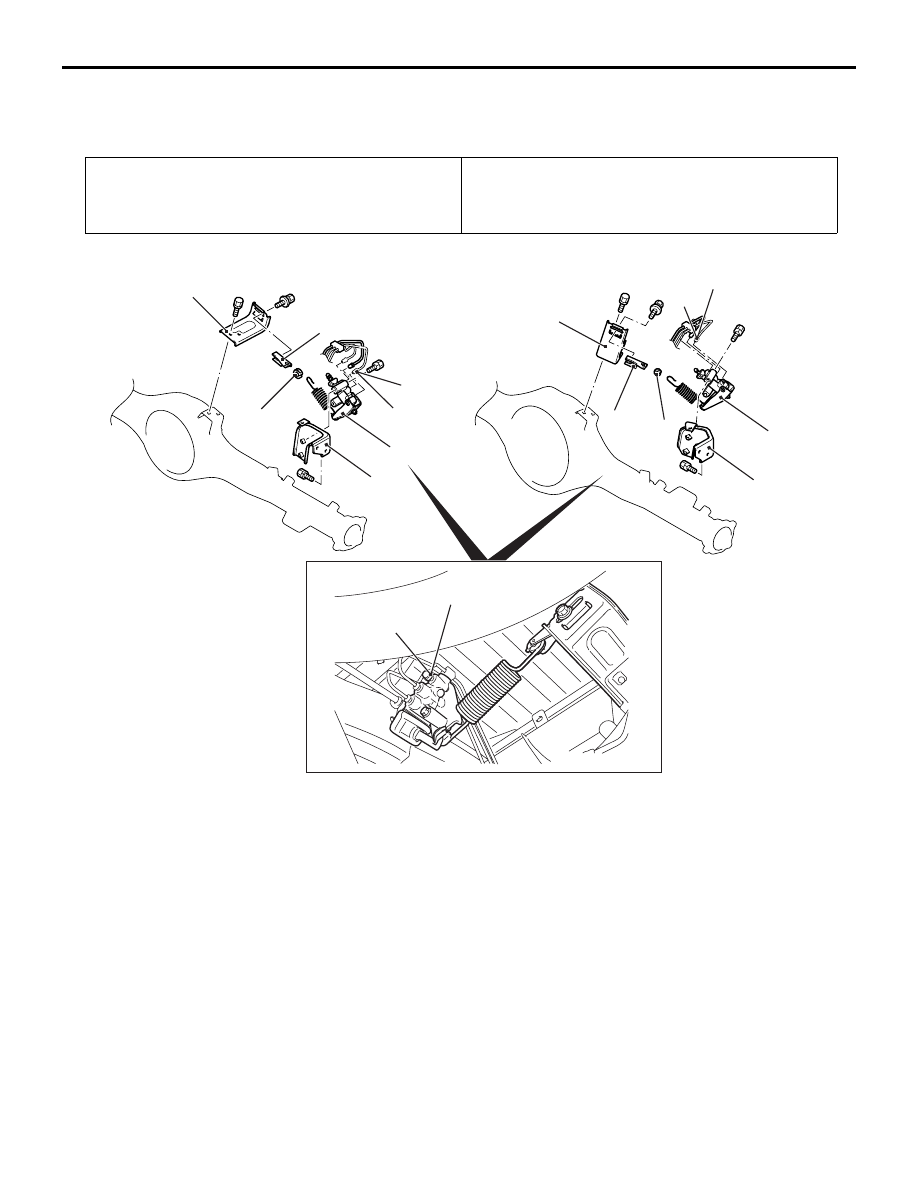
LOAD-SENSING PROPORTIONING VALVE
BASIC BRAKE
35A-28
LOAD-SENSING PROPORTIONING VALVE
REMOVAL AND INSTALLATION
M1351005400134
Pre-removal Operation
Brake fluid draining
Post-installation Operation
• Brake fluid supplying and air bleeding (Refer to
).
• Load sensing spring length check (Refer to
ACA00566AB
1
2
3
5
6
4
15 ± 2 N·m
1
2
3
5
6
4
15 ± 2 N·m
<2WD (except High rider)>
<2WD (High rider), 4WD>
7.8 ± 1.0 N·m
Bleeder screw
Removal steps
1.
Spring support
2.
Spring holder
3.
Bracket
4.
Brake tube connection
5.
Load sensing proportioning valve
6.
Bracket
Removal steps (Continued)