Mitsubishi L200. Manual - part 383


  Index      Mitsubishi     Mitsubishi L200 - service repair manual 2012 year


Search            


Content   ..  381  382  383  384   ..


Mitsubishi L200. Manual - part 383


AC500718

AB

MB990890
or
MB990891

Housing
tube

DIFFERENTIAL CARRIER AND FREE WHEELING CLUTCH <4WD>

FRONT AXLE

26-37

CAUTION

Place the special tool against the outer race of 
the bearing.
2. Use special tool rear suspension housing base 

(MB990890 or MB990891) to press-fit the bearing 
to the side of the clutch housing.

>>C<<OIL SEAL INSTALLATION

ACX01029AC

Oil seal

MB990938

MB990926

Housing tube

Use the following special tools to press-fit the oil seal 
to the clutch housing.

• Installer adapter (MB990926)

• Bar (MB990938)

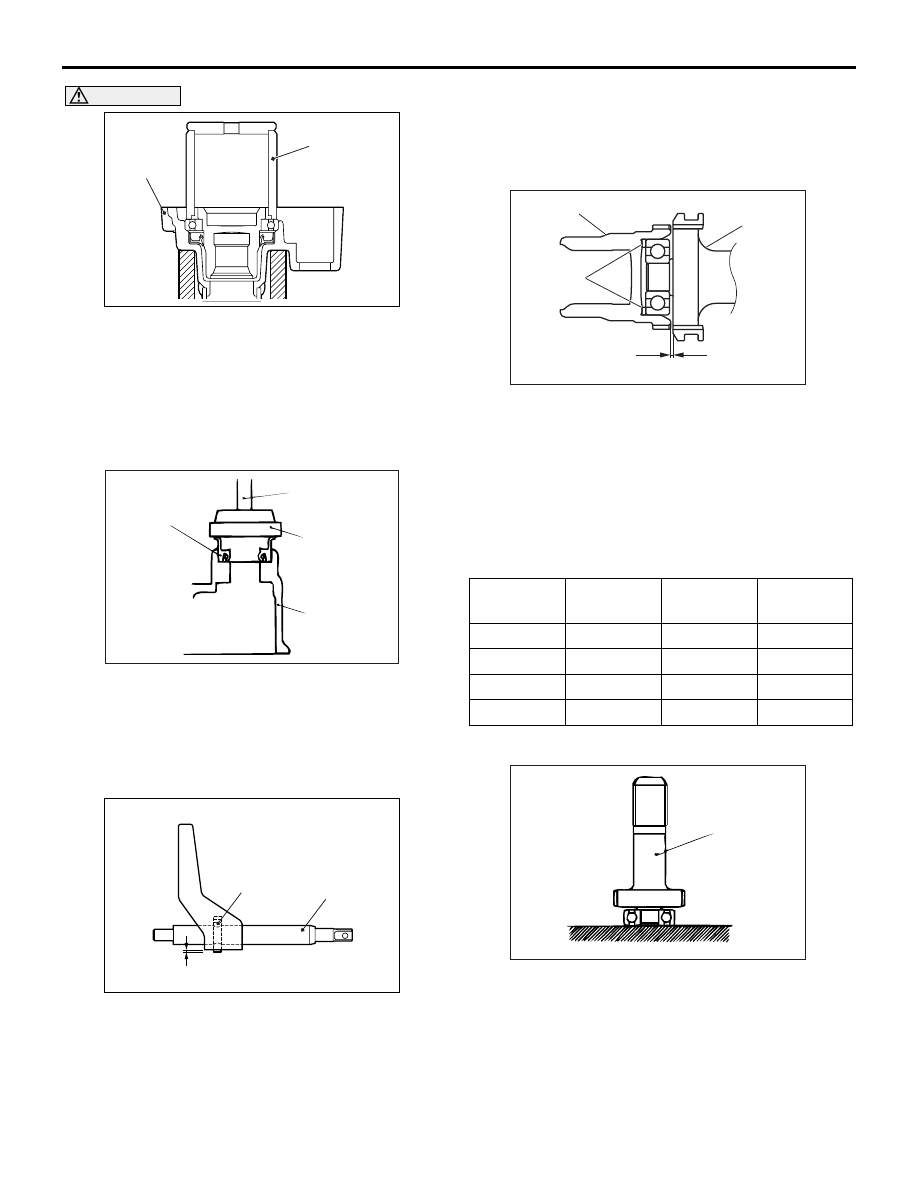
>>D<< SPRING PIN INSTALLATION

AC500719

AB

Spring pin

Shift rod

0 – 1 mm

Tap the spring pin from the chamfered side of the 
shaft rod until the projection length becomes the 
length shown in the illustration.

>>E<< SPACER INSTALLATION

AC101906AB

Clutch gear

Main shaft
assembly

Spacer

A

1. Place the current spacer in the area shown in the 

illustration to check that the dimensions shown in 
the illustration are within the standard values.

Standard Value (A): 0.05 

 0.3 mm

2. If the dimensions are outside of the standard 

values, select the correct spacer type to fit in the 
standard values.
Spacer type 

Part 
Number

Thickness 
mm

Part 
Number

Thickness 
mm

MR111526 1.1

MR111530 2.1

MR111527 1.35

MR111531 2.35

MR111528 1.6

MR111532 2.6

MR111529 1.85

MR111533 2.85

>>F<< BEARING/MAIN SHAFT INSTALLATION

ACX01031AB

Main shaft

Press-fit the bearing to the shoulder of the mainshaft.

DIFFERENTIAL CARRIER AND FREE WHEELING CLUTCH <4WD>

FRONT AXLE

26-38

DISASSEMBLY

M1262002300146

AC500723AC

17

23

24

25

27

22

18

17

16

10

11

12

8

9

13

7

14

6

5

34

1

2

26

29

28 21 20

33

30

N

N

N

4

3

N

N

32

31

15

16

18

19


Disassembly steps 

<<

A

>>


Inspection before disassembly

1.  Filler plug
2.  Gasket
3.  Drain plug
4.  Packing
5.  Differential cover
6. Vent plug <Vehicles with Easy select 

4WD>

7. Bearing cap

<<

B

>>

8. Differential case assembly

<<

B

>>


9.  Differential side bearing adjusting spacer

<<

B

>>

10.  Differential side bearing outer race

<<

C

>>


11.  Differential side bearing inner race

<<

D

>>


12.  Drive gear

<<

E

>>


13.  Lock pin
14. Pinion shaft
15. Pinion gear
16. Pinion washer
17. Side gear
18. Side gear spacer
19. Differential case

<<

F

>>


20.  Self-locking nut
21.  Washer

<<

G

>>


22.  Drive pinion assembly
23. Drive pinion front shim (for turning torque 

adjustment)

24. Drive pinion spacer

<<

H

>>

25. Drive pinion rear bearing inner race
26. Drive pinion rear shim (For pinion height 

adjustment)

27. Drive pinion

28. Companion flange
29. Oil seal
30. Drive pinion front bearing inner race

<<

I

>>

31. Drive pinion front bearing outer race

<<

J

>>

32. Drive pinion rear bearing outer race

<<

K

>>


33.  Oil seal


34.  Differential carrier

DISASSEMBLY SERVICE POINTS

<<A>> INSPECTION BEFORE DISASSEMBLY
1. Remove the cover.

AC102883

MB990909
and
MB991116

AC

2. Hold the following special tools in a vise, and 

install the differential carrier assembly to the 
special tool.

• Working base (MB990909)

• Working base adapter (MB991116)


Disassembly steps (Continued)

DIFFERENTIAL CARRIER AND FREE WHEELING CLUTCH <4WD>

FRONT AXLE

26-39

DRIVE GEAR BACKLASH

ACX01034AB

1. With the drive pinion locked in place, use a dial 

gauge to measure the drive gear backlash in four 
or more places on the drive gear.

Standard value: 0.11 

 0.16 mm

2. If the backlash is not within the standard value, 

adjust the final drive gear backlash (Refer to ).

3. After the adjustment, inspect the final drive gear 

tooth contact.

DRIVE GEAR RUNOUT

ACX01036 AB

1. Measure the drive gear runout at the shoulder on 

the reverse side of the drive gear.

Limit: 0.05 mm

2. When the runout exceeds the limit value, check 

for foreign material between drive gear rear side 
and differential case, and for loose drive gear 
installation bolts.

3. When check (2) gives normal results, reposition 

drive gear and differential case and remeasure.

4. If adjustment is impossible, replace differential 

case, or replace drive gear and pinion as a set.

DIFFERENTIAL GEAR BACKLASH

AC102885

Wedge

Side gear
spacer

AC

Side gear
spacer

1. Insert a wedge between the side gear and the 

pinion shaft to lock the side gear.

2. While locking the side gear with the wedge, 

measure the differential gear backlash with a dial 
indicator on the pinion gear.
Use the measurement procedure for the other 
pinion gear.

Standard value: 0.01 

 0.250 mm

3. If the backlash exceeds the standard value, adjust 

it by replacing the side gear spacers.

4. If adjustment is not possible, replace the side 

gears and pinion gears as a set.

DRIVE GEAR TOOTH CONTACT
Check the tooth contact of drive gear by following the 
steps below.

ACX01037 AB

1. Apply a thin, uniform coat of machine blue to both 

surfaces of the drive gear teeth.

DIFFERENTIAL CARRIER AND FREE WHEELING CLUTCH <4WD>

FRONT AXLE

26-40

CAUTION

If the drive gear is rotated too much, the tooth 
contact pattern will become unclear and difficult 
to check.

AC102888

MB990939

AC

2. Insert special tool remover bar (MB990939) 

between the differential carrier and the differential 
case, and then rotate the companion flange by 
hand (once in the normal direction, and then once 
in the reverse direction) while applying a load to 
the drive gear so that the revolution torque 
(approximately 2.5 

− 3.0 N⋅m) is applied to the 

drive pinion.

3. Check the tooth contact condition of the drive gear 

and drive pinion.

Standard tooth contact pattern

Problem

Solution

1. Narrow tooth side
2. Drive-side tooth surface 


    (the side applying power during forward


    movement)
3. Wide tooth side
4. Coast-side tooth surface 


    (the side applying power during reverse


    movement)
   

ACX01039 AF

1

3

4

2

Tooth contact pattern resulting 
from excessive pinion 
height

AC107260

1

2

3

4

AB

The drive pinion is positioned too 
far from the centre of the drive 
gear.

AC107261AB

1

2

3

4

Increase the thickness of 
the drive pinion rear shim, 
and position the drive pinion 
closer to the centre of the 
drive gear. Also, for 
backlash adjustment, 
position the drive gear 
farther from the drive 
pinion.

Tooth contact pattern resulting 
from insufficient pinion 
height.

AC107262

1

2

3

4

AB

The drive pinion is positioned too 
close to the centre of the drive 
gear.

AC107263

1

2

3

4

AB

Decrease the thickness of 
the drive pinion rear shim, 
and position the drive pinion 
farther from the centre of 
the drive gear. Also, for 
backlash adjustment, 
position the drive gear 
closer to the drive pinion.

NOTE: Check the tooth contact pattern to confirm 
that the adjustments of the pinion height and 
backlash have been done properly. Continue to 
adjust the pinion height and backlash until the 
tooth contact pattern resembles the standard pat-

tern. If, even after adjustments have been made, 
the correct tooth contact pattern cannot be 
obtained, it means that the drive gear and the 
drive pinion have become worn beyond the allow-
able limit. Replace the gear set.


Content   ..  381  382  383  384   ..