Mitsubishi L200. Manual - part 301
ON-VEHICLE SERVICE
AUTOMATIC TRANSMISSION
23A-111
WAVEFORM SAMPLE
AC001874
(V)
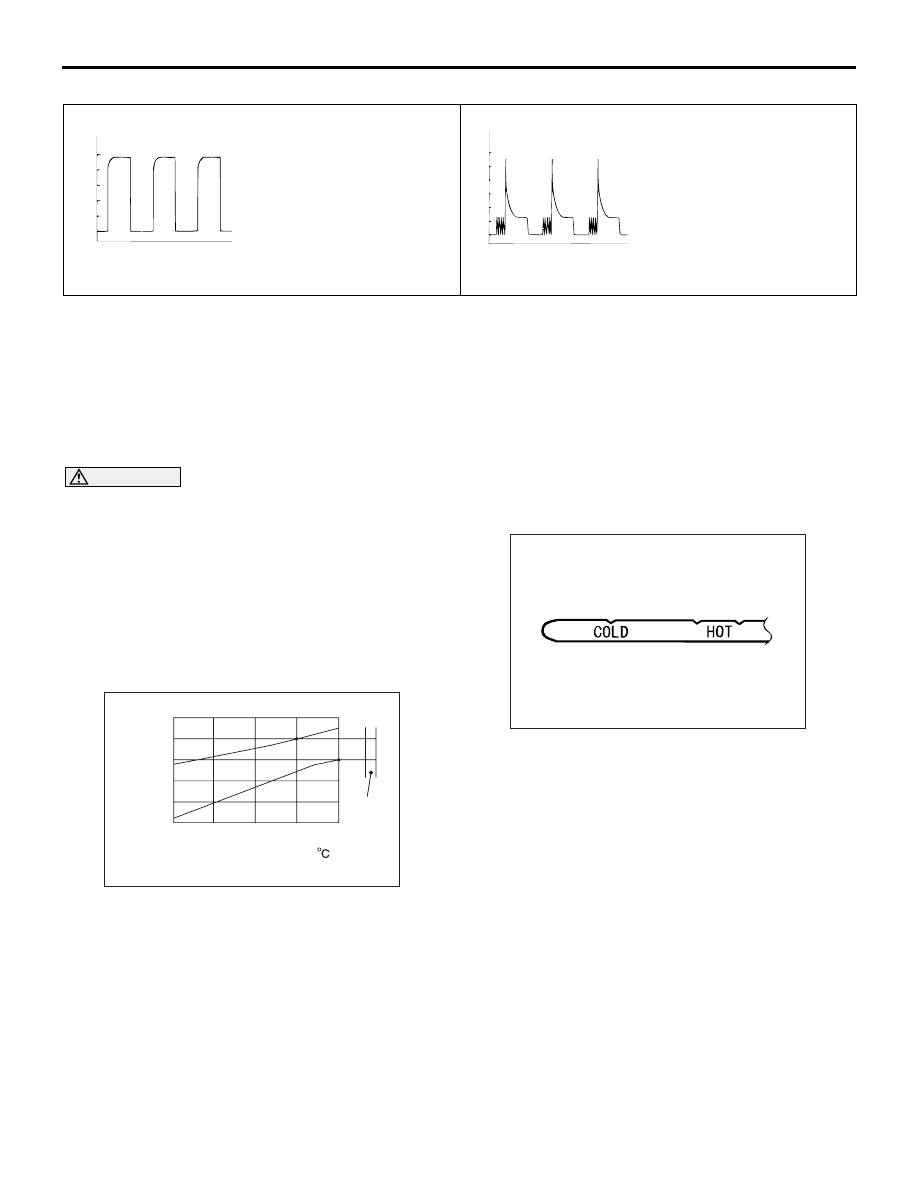
Waveform A
0
5
AH
(ms)
AC001875
(V)
Waveform B
0
20
40
60
AJ
(ms)
ON-VEHICLE SERVICE
ESSENTIAL SERVICE
A/T FLUID CHECK
M1231103700212
CAUTION
When replacing the transmission with a new one,
overhauling the existing transmission, or driving
in a harsh condition, the A/T fluid cooler line
should always be flushed out and A/T fluid
should be replaced with a new one.
1. Drive the vehicle until the A/T fluid temperature
reaches the normal temperature (70
− 80°C)
NOTE: Measure A/T fluid temperature using
M.U.T.III.
NOTE:
AC503813
Fluid level
[mm]
A/T fluid temperature [ ]
10
0
-10
-20
-30
40
60
80
Gauge
AB
-40
HO
T
Check the fluid level referring to the characteris-
tics chart shown at left if it takes some time to
reach the normal operation temperature of A/T
fluid (70
−
80
°
C).
2. Park the vehicle on a level surface.
3. Move the selector lever to all positions to fully
charge the torque converter and the fluid lines
with A/T fluid, and then move the selector lever to
the P position.
4. After wiping away any dirt from around the oil
level gauge, pull out the oil level gauge and check
the level of A/T fluid.
NOTE: If the A/T fluid has a burnt smell, or if it has
become very contaminated or dirty, it means that
the A/T fluid has become contaminated by minute
particles form bushings (metal) or worn parts. In
such a case, the transmission needs to be over-
hauled and the A/T fluid cooler line needs to be
flushed out.
AC000846 AB
5. Check that the A/T fluid level is between the HOT
marks on the oil level gauge. If the A/T fluid level
is too low, add more A/T fluid until the level
reaches between the HOT marks.
Automatic transmission fluid: DIA QUEEN
ATF SP III
NOTE: If the A/T fluid level is too low, the oil pump
draws air into the system along with the A/T fluid,
and air bubbles will thus from in the fluid circuit.
This will cause a drop in fluid pressure and cause
the shift points to change and the clutches and
brakes to slip.
If the A/T fluid level is too high, the gear will churn
the A/T fluid and cause bubbles to develop, which
can then cause the same problems as when the
A/T fluid is too low.
In either case, the air bubbles can cause over-
heating and oxidation of the A/T fluid, and also