Mitsubishi L200. Manual - part 298


  Index      Mitsubishi     Mitsubishi L200 - service repair manual 2012 year


Search            


Content   ..  296  297  298  299   ..


Mitsubishi L200. Manual - part 298


TROUBLESHOOTING

AUTOMATIC TRANSMISSION

23A-99

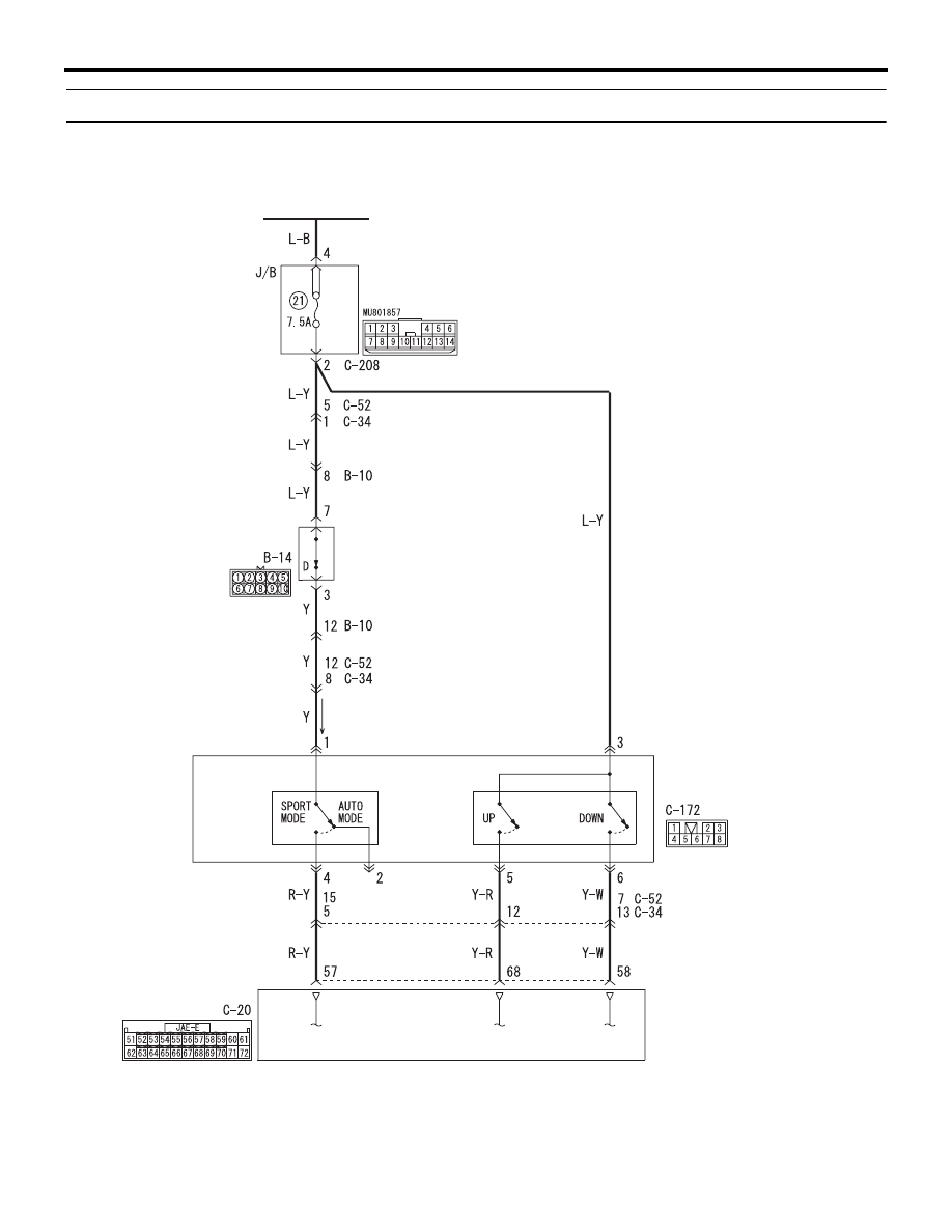
Inspection Procedure 18: Shift Switch Assembly System <5A/T>

IGNITION 
SWITCH (IG1)

A/T-ECU

SHIFT
SWITCH
ASSEMBLY

SELECT
SWITCH

SHIFT
SWITCH

Wire colour code 
B : Black     LG : Light green     G : Green     L : Blue     W : White     Y : Yellow     SB : Sky blue 
BR : Brown     O : Orange     GR : Grey     R : Red     P : Pink     V : Violet     PU : Purple     SI : Silver

INHIBITOR 
SWITCH

Shift Switch System Circuit

AC903920

<LHD>
<RHD>

<LHD>
<RHD>

<LHD>
<RHD>

<LHD>
<RHD>

AC510056AD

Harness side

B-10 (B)

Connector: B-10

AC510056AG

B-14 (B)

Connector: B-14

Harness side

AC510057

Harness side

A/T-ECU

C-20

AC

Connector: C-20

A/T-ECU

<RHD>

<LHD>

AC509930AG

Connector: C-34 <RHD>

C-34

Harness side

AC509613AG

Connector: C-52 <LHD>

C-52

Harness side

AC903865AM

Connector: C-172 <RHD>

C-172

AC903853

BF

Connector: C-172 <LHD>

C-172

AC509934

Connectors: C-208 <LHD>

Junction block (Front view)

C-208

AH

Harness side

TROUBLESHOOTING

AUTOMATIC TRANSMISSION

23A-100

OPERATION
The shift switch assembly detects the shift range 
(sport mode) which the driver has selected, and 
sends the information to the A/T-ECU.

COMMENTS ON TROUBLE SYMPTOM
The cause is probably a malfunction of the shift 
switch and A/T-ECU.

TROUBLESHOOTING

AUTOMATIC TRANSMISSION

23A-101

PROBABLE CAUSES

• Malfunction of shift switch assembly

• Damaged harness wires and connectors

• Malfunction of the A/T-ECU

DIAGNOSIS PROCEDURE

STEP 1. M.U.T.-III diagnosis code
Either of diagnosis codes P1770 or P1771 is set, 
inhibitor switch is defective.

Q: Are diagnosis codes P1770 or P1771 output?

YES <diagnosis code P1770 is set> : 

Refer to 

diagnosis code P1770: Inhibitor switch 
system 

P.23A-49

.

YES <diagnosis code P1771 is set> : 

Refer to 

diagnosis code P1771: Inhibitor switch 
system 

P.23A-52

.

NO : 

Go to Step 2.

STEP 2. M.U.T.-III data list

• Item 27: Select switch

• Item 28: Shift switch (Up)

• Item 29: Shift switch (Down)

(Refer to data list reference table 

P.23A-103

).

Q: Is the check result normal?

YES : 

Intermittent malfunction (Refer to GROUP 

00 

− How to Cope with Intermittent 

Malfunction ).

NO <"NG" for all items> : 

Go to Step 3.

NO <"NG" for items 28 and 29> : 

Go to Step 5.

NO <"NG" for item 27> : 

Go to Step 10.

NO <"NG" for item 28> : 

Go to Step 17.

NO <"NG" for item 29> : 

Go to Step 20.

STEP 3. Connectors check: C-172 shift switch 
assembly connector, C-20 A/T-ECU connector.
Check for the contact with terminals.

Q: Is the check result normal?

YES : 

Go to Step 4.

NO : 

Repair the defective connector.

STEP 4. M.U.T.-III data list

• Item 27: Select switch

• Item 28: Shift switch (Up)

• Item 29: Shift switch (Down)

Check the above data list (Refer to data list reference 
table 

P.23A-103

). 

Q: Is the check result normal?

YES : 

Intermittent malfunction (Refer to GROUP 

00 

− How to Cope with Intermittent 

Malfunction ).

NO : 

Replace the A/T-ECU.

STEP 5. Check the shift switch assembly.
Refer to 

P.23A-134

.

Q: Is the check result normal?

YES : 

Go to Step 6.

NO : 

Replace the shift lever assembly.

STEP 6. Connector check: C-172 shift switch 
assembly connector
Check for the contact with terminals.

Q: Is the check result normal?

YES : 

Go to Step 7.

NO : 

Repair the defective connector.

STEP 7. Measure the voltage at shift switch 
assembly connector C-172.
(1) Disconnect the connector, and measure the 

voltage between terminal 3 and earth at the 
wiring harness side.

(2) Ignition switch: ON

OK: System voltage

Q: Is the check result normal?

YES : 

Go to Step 4.

NO : 

Go to Step 8.

STEP 8. Connectors check: C-208 J/B connector
Check for the contact with terminals.

Q: Is the check result normal?

YES : 

Go to Step 9.

NO : 

Repair the defective connector.

STEP 9. Check the harness between shift switch 
assembly connector C-172 terminal No.3 and J/B 
connector C-208 terminal No.2.
Check the power supply line for short or open circuit.

Q: Is the check result normal?

YES : 

Go to Step 4.

NO : 

Repair the wiring harness.

STEP 10. Check the shift switch assembly.
Refer to 

P.23A-134

.

Q: Is the check result normal?

YES : 

Go to Step 11.

NO : 

Replace the shift lever assembly.

TROUBLESHOOTING

AUTOMATIC TRANSMISSION

23A-102

STEP 11. Connector check: C-172 shift switch 
assembly connector
Check for the contact with terminals.

Q: Is the check result normal?

YES : 

Go to Step 12.

NO : 

Repair the defective connector.

STEP 12. Measure the voltage at shift switch 
assembly connector C-172
(1) Disconnect the connector, and measure the 

voltage between terminal 1 and earth at the 
wiring harness side.

(2) Selector lever position: D
(3) Ignition switch: ON

OK: System voltage

Q: Is the check result normal?

YES : 

Go to Step 13.

NO  : 

Go to Step 15.

STEP 13. Connectors check: C-20 A/T-ECU 
connector, C-34 <RHD> or C-52 <LHD> 
intermediate connector
Check for the contact with terminals.

Q: Is the check result normal?

YES : 

Go to Step 14.

NO : 

Repair the defective connector.

STEP 14. Check the harness between shift switch 
assembly connector C-172 terminal No.4 and A/T-
ECU connector C-20 terminal No.57.
Check the output line for short-circuited or open cir-
cuit.

Q: Is the check result normal?

YES : 

Go to Step 15.

NO : 

Repair the wiring harness.

STEP 15. Connector check: B-10, C-34 <RHD> or 
C-52 <LHD> intermediate connector
Check for the contact with terminals.

Q: Is the check result normal?

YES : 

Go to Step 16.

NO : 

Repair the defective connector.

STEP 16. Check the harness between shift switch 
assembly connector C-172 terminal No.1 and 
inhibitor switch connector B-14 terminal No.3.
Check the power supply line for short or open circuit.

Q: Is the check result normal?

YES : 

Go to Step 4.

NO : 

Repair the wiring harness.

STEP 17. Check the shift switch assembly.
Refer to 

P.23A-134

.

Q: Is the check result normal?

YES : 

Go to Step 18.

NO : 

Replace the shift switch assembly.

STEP 18. Connectors check: C-172 shift switch 
assembly connector, C-20 A/T-ECU connector 
and C-34 <RHD> or C-52 <LHD> intermediate 
connector
Check for the contact with terminals.

Q: Is the check result normal?

YES : 

Go to Step 19.

NO : 

Repair the defective connector.

STEP 19. Check the harness between shift switch 
assembly connector C-172 terminal No.6 and A/T-
ECU connector C-20 terminal No.58.
Check the output line for short-circuited or open cir-
cuit.

Q: Is the check result normal?

YES : 

Go to Step 4.

NO : 

Repair the wiring harness.

STEP 20. Check the shift switch assembly.
Refer to 

P.23A-134

.

Q: Is the check result normal?

YES : 

Go to Step 21.

NO : 

Replace the shift switch assembly.

STEP 21. Connectors check: C-172 shift switch 
assembly connector, C-20 A/T-ECU connector 
and C-34 <RHD> or C-52 <LHD> intermediate 
connector
Check for the contact with terminals.

Q: Is the check result normal?

YES : 

Go to Step 22.

NO : 

Repair the defective connector.

STEP 22. Check the harness between shift switch 
assembly connector C-172 terminal No.5 and A/T-
ECU connector C-20 terminal No.68.
Check the output line for short-circuited or open cir-
cuit.

Q: Is the check result normal?

YES : 

Go to Step 4.

NO : 

Repair the wiring harness.


Content   ..  296  297  298  299   ..