Mitsubishi L200. Manual - part 281
TROUBLESHOOTING
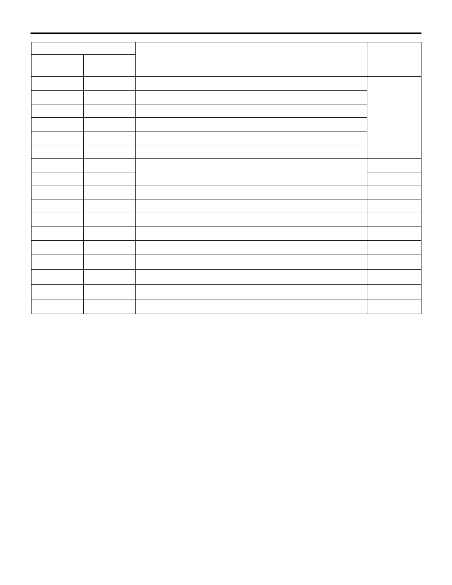
AUTOMATIC TRANSMISSION
23A-31
NOTE:
*
: When the diagnosis code related to the
CAN communication error is set, check the vehicle
equipment. If this system is not equipped, the diag-
nosis code is always set, but it is not abnormal.
P1779
−
1st gear ratio does not meet the specification
<4A/T>
<5A/T>
P1780
−
2nd gear ratio does not meet the specification
P1781
−
3rd gear ratio does not meet the specification
P1782
−
4th gear ratio does not meet the specification
P1783
−
5th gear incorrect ratio <5A/T>
P1784
−
Reverse gear ratio does not meet the specification
P1786
−
DCC solenoid valve system
P1787
−
P1788
P1751
A/T control relay system
P1790
−
Back up line system
P1901
−
Can signal time-out (Engine-ECU)
U1073
−
Bus Off
U1100
*
−
Engine-ECU time-out (related to engine)
U1102
*
−
ASTC-ECU time-out
U1109
*
−
ETACS-ECU time-out
U1120
*
−
Failure information of Engine-ECU
U1190
*
−
Can’t receive fault detection control signal
Diagnosis code No.
Diagnosis item
Reference
page
M.U.T.-III
General
scan tool