Mitsubishi L200. Manual - part 270
2-4WD SYNCHRONIZER <V5MB1-J-ND2, NEZ, PD2>
MANUAL TRANSMISSION OVERHAUL <V5MB1>
22C-65
2-4WD SYNCHRONIZER <V5MB1-J-ND2, NEZ, PD2>
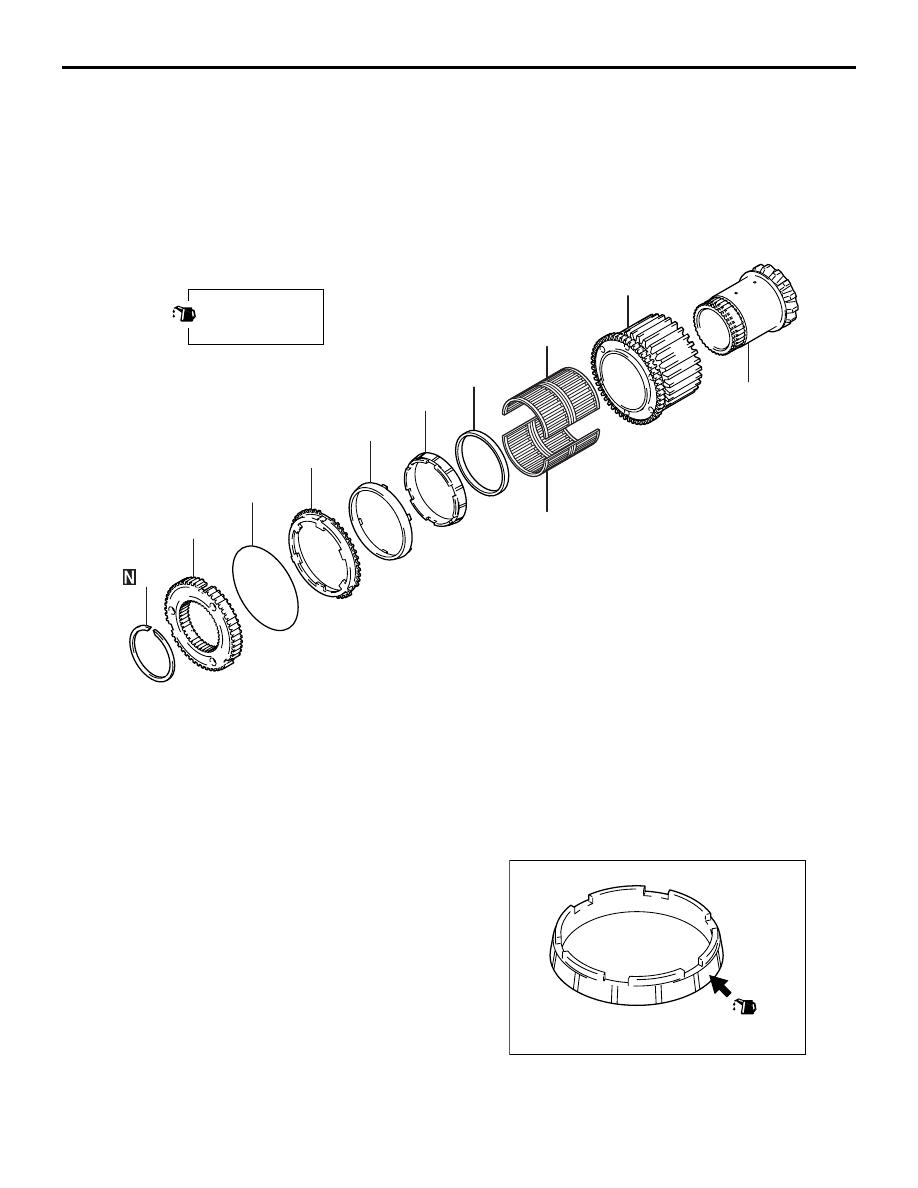
DISASSEMBLY AND REASSEMBLY
M1222010900020
AK503423
4
5
6
1
2
3
7
9
9
8
10
AB
Apply gear oil to
all moving parts
before installation.
Disassembly steps
>>
C
<< 1.
Snap ring
2.
2-4WD Synchronizer hub
3.
2-4WD Synchronizer spring
>>
B
<< 4.
Outer synchronizer ring
5.
Synchronizer cone
>>
A
<< 6.
Inner synchronizer ring
7.
Drive sprocket
8.
Bearing spacer
9.
Needle bearing
10. Front side gear
REASSEMBLY SERVICE POINTS
>>A<< INNER SYNCHRONIZER RING INSTALLA-
TION
AK503426AB
Apply oil the synchronizer ring cone surface before
installation.