Mitsubishi L200. Manual - part 228
ACB01742
23
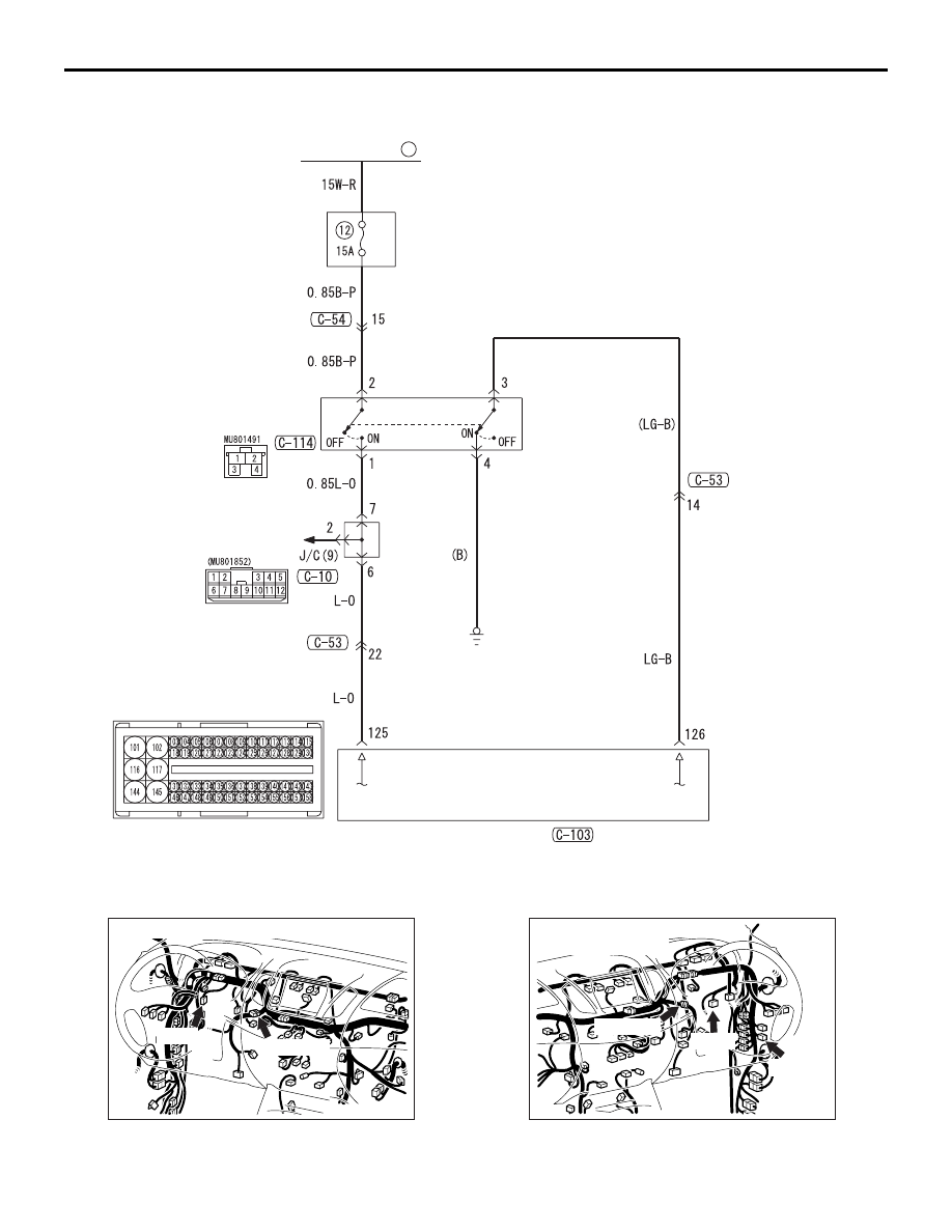
FUSIBLE LINK
RELAY
BOX
STOP LAMP
STOP LAMP
SWITCH
ENGINE-ECU
Wire colour code
B : Black LG : Light green G : Green L : Blue W : White Y : Yellow SB : Sky blue
BR : Brown O : Orange GR : Grey R : Red P : Pink V : Violet PU : Purple SI : Silver
Stop Lamp Switch System Circuit (Except EURO 5)
ACA01405
Connectors: C-10, C-114 <LH drive vehicles>
AB
C-10 (GR)
C-114
ACA01406
C-120 (L)
AB
C-10 (GR)
C-114
Connectors: C-10, C-114, C-120
<RH drive vehicles>
CRUISE CONTROL
ENGINE AND EMISSION CONTROL
17-16