Mitsubishi L200. Manual - part 140


  Index      Mitsubishi     Mitsubishi L200 - service repair manual 2012 year


Search            


Content   ..  138  139  140  141   ..


Mitsubishi L200. Manual - part 140


TROUBLESHOOTING

DIESEL FUEL

13A-356

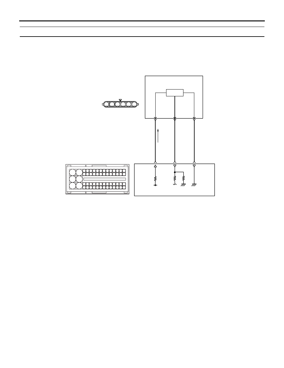
Code No. P2128: Accelerator Pedal Position Sensor (sub) Circuit High Input

OPERATION

• A power voltage of 5 V is applied to the accelera-

tor pedal position sensor (terminal No. 4) from the 
engine-ECU (terminal No. 134).

• The power voltage is earthed to the engine-ECU 

(terminal No. 136) from the accelerator pedal 
position sensor (terminal No. 5).

• The sensor signal is inputted to the engine-ECU 

(terminal No. 135) from the accelerator pedal 
position sensor output terminal (terminal No. 6).

FUNCTION

• The accelerator pedal position sensor (sub) out-

puts voltage which corresponds to the accelera-
tor pedal depression.

• The engine-ECU checks whether the voltage is 

within a specified range.

TROUBLE JUDGMENT

Check Conditions

• Battery positive voltage is 6 − 16 V

• 2 seconds later after the ignition switch has been 

in "ON" position or the engine has started up

• Accelerator pedal position sensor (main) is nor-

mal

• Accelerator pedal position sensor (main) output 

voltage is 0.2 V or higher and 2.8 V or lower.

Judgment Criterion

• Accelerator pedal position sensor (main) output 

voltage exceeds 2.4 V for 0.3 seconds.

PROBABLE CAUSES

• Failed accelerator pedal position sensor

• Open circuit in accelerator pedal position sensor 

circuit or loose connector contact

• Failed engine-ECU

AKA00110

6

1 2 3 4 5

101 102

103104 105 106107 108109 110 111112 113 114115

118119 120 121122 123124 125126127 128 129130

131132 133 134135 136137 138139140 141142 143

146147 148 149150 151152 153154155 156 157158

117

145

116

144

Accelerator Pedal Position Sensor (sub) Circuit

(sub)

Hall IC

Accelerator
pedal
position
sensor

C-115

(MU805200)

4

134

5 V

Y-R

6

135

L

5

136

B-Y

C-103

Wire colour code
B: Black  LG: Light green  G: Green  L: Blue  W: White  Y: Yellow  SB: Sky blue  BR: Brown  O: Orange  GR: Grey
R: Red  P: Pink  V: Violet  PU: Purple  SI: Silver

Engine-ECU

AB

TROUBLESHOOTING

DIESEL FUEL

13A-357

DIAGNOSIS PROCEDURE

STEP 1. M.U.T.-III data list

• Refer to Data List Reference Table 

P.13A-542

.

a. Item 10: Accelerator pedal position sensor 

(sub)

Q: Is the check result normal?

YES : 

Intermittent malfunction (Refer to GROUP 

00 

− How to Use Troubleshooting/

Inspection Service Points 

− How to Cope 

with Intermittent Malfunctions ).

NO : 

Go to Step 2 .

STEP 2. Connector check: C-115 accelerator 
pedal position sensor connector

Q: Is the check result normal?

YES : 

Go to Step 3 .

NO : 

Repair or replace the connector.

STEP 3. Perform resistance measurement at C-
115 accelerator pedal position sensor connector.

• Disconnect connector, and measure at harness 

side.

• Resistance between terminal No. 5 and earth.

OK: Continuity (2 

 or less)

Q: Is the check result normal?

YES : 

Go to Step 7 .

NO : 

Go to Step 4 .

AK700804

1

6 5 4 3 2

C-115 (B)

C-115 (B)

Connector: C-115

<R.H. drive vehicles>

<L.H. drive vehicles>

AB

Harness side connector

AK700804

1

6 5 4 3 2

C-115 (B)

C-115 (B)

Connector: C-115

<R.H. drive vehicles>

<L.H. drive vehicles>

AB

Harness side connector

TROUBLESHOOTING

DIESEL FUEL

13A-358

STEP 4. Connector check: C-103 engine-ECU 
connector

Q: Is the check result normal?

YES : 

Go to Step 5 .

NO : 

Repair or replace the connector.

STEP 5. Check harness between C-115 (terminal 
No. 5) accelerator pedal position sensor 
connector and C-103 (terminal No. 136) engine-
ECU connector.

• Check earthing line for open circuit.

Q: Is the check result normal?

YES : 

Go to Step 6 .

NO : 

Repair the damaged harness wire.

AKA00090

101

102

103

104

105

106

107

108

109

110

111

112

113

114

115

118

119

120

121

122

123

124

125

126

127

128

129

130

131

132

133

134

135

136

137

138

139

140

141

142

143

146

147

148

149

150

151

152

153

154

155

156

157

158

117

145

116

144

C-103 (B)

C-103 (B)

<R.H. drive vehicles>

Harness side connector

<L.H. drive vehicles>

Connector: C-103

AB

AK700804

1

6 5 4 3 2

C-115 (B)

C-115 (B)

Connector: C-115

<R.H. drive vehicles>

<L.H. drive vehicles>

AB

Harness side connector

AKA00090

101

102

103

104

105

106

107

108

109

110

111

112

113

114

115

118

119

120

121

122

123

124

125

126

127

128

129

130

131

132

133

134

135

136

137

138

139

140

141

142

143

146

147

148

149

150

151

152

153

154

155

156

157

158

117

145

116

144

C-103 (B)

C-103 (B)

<R.H. drive vehicles>

Harness side connector

<L.H. drive vehicles>

Connector: C-103

AB

TROUBLESHOOTING

DIESEL FUEL

13A-359

STEP 6. M.U.T.-III data list

• Refer to Data List Reference Table 

P.13A-542

.

a. Item 10: Accelerator pedal position sensor 

(sub)

Q: Is the check result normal?

YES : 

Intermittent malfunction (Refer to GROUP 

00 

− How to Use Troubleshooting/

Inspection Service Points 

− How to Cope 

with Intermittent Malfunctions ).

NO : 

Replace the engine-ECU. When the engine-
ECU is replaced, write the chassis number 
(Refer to GROUP 00 

− Precautions Before 

Service 

− How to Perform Chassis Number 

Writing ). After replacing the engine-ECU, 
register the injector identification code and 
learn fuel injection (Refer to GROUP 00 

− 

Precautions Before Service 

− What The 

Common Rail Engine Learns ). After 
registering the injector identification code, 
the vehicle equipped with the DPF carries 
out the forcible DPF regeneration. (Refer to 
GROUP 17 

− Emission Control − Diesel 

Particulate Filter (DPF) System 

− Forcible 

DPF Regeneration ).

STEP 7. Replace the accelerator pedal position 
sensor

• After replacing the accelerator position sensor, 

re-check the trouble symptoms.

Q: Is the check result normal?

YES : 

The check is end.

NO : 

Replace the engine-ECU. When the engine-
ECU is replaced, write the chassis number 
(Refer to GROUP 00 

− Precautions Before 

Service 

− How to Perform Chassis Number 

Writing ). After replacing the engine-ECU, 
register the injector identification code and 
learn fuel injection (Refer to GROUP 00 

− 

Precautions Before Service 

− What The 

Common Rail Engine Learns ). After 
registering the injector identification code, 
the vehicle equipped with the DPF carries 
out the forcible DPF regeneration. (Refer to 
GROUP 17 

− Emission Control − Diesel 

Particulate Filter (DPF) System 

− Forcible 

DPF Regeneration ).

Code No. P2138: Accelerator Pedal Position Sensor (Main and Sub) Range/Performance Problem

OPERATION

• Refer to Code No. P2122: Accelerator Pedal 

Position Sensor (main) Circuit Low Input 

P.13A-

333

.

• Refer to Code No. P2127: Accelerator Pedal 

Position Sensor (sub) Circuit Low Input 

P.13A-

349

.

FUNCTION

• Engine-ECU checks the accelerator pedal posi-

tion sensor output signal characteristics for 
abnormal conditions.

TROUBLE JUDGMENT

Check Condition

• Ignition switch is in "ON" position.

Judgment Criterion

• When an error is detected on the High side of the 

accelerator pedal position (main) for 0.1 second, 
the accelerator pedal position sensor (sub) is 
faulty on the High/Low side.

Check Conditions

• Battery positive voltage is 6 − 16 V

• 2 seconds later after the ignition switch has been 

in "ON" position or the engine has started up

• Engine speed is 600 r/min or more.

• Accelerator pedal position sensor (main) output 

voltage is 0.2 V or higher and 4.8 V or lower.

• Accelerator pedal position sensor (sub) output 

voltage is 0.125 V or higher and 2.375 V or lower.

Judgment Criterion

• When a change in the accelerator pedal position 

sensor (sub) output voltage is less than the spec-
ified value for 0.2 second, the difference between 
the opening indicated by the accelerator pedal 
position sensor (main) and that by the accelerator 
pedal position sensor (sub) is 18 % or more of the 
specified value.

PROBABLE CAUSES

• Failed accelerator pedal position sensor

• Accelerator pedal position sensor circuit harness 

damage or loose connector contact

• Failed engine-ECU


Content   ..  138  139  140  141   ..