Mitsubishi L200. Manual - part 124
TROUBLESHOOTING
DIESEL FUEL
13A-292
OPERATION
• The electrical current source is supplied from the
engine control relay (terminal No. 3) to the glow
control unit (terminal No. 6). Also, it is supplied
from the glow control unit (terminal No.7) to the
body earth.
• The request signal of operating the glow plug is
input into the glow control unit (terminal No. 1)
from the engine-ECU (terminal No.120).
• The voltage for the glow plug is applied from the
battery to the glow control unit (terminal No. 10).
• The voltage is applied from the glow control unit
(terminal No.1, 2, 3 and 4) to each glow plug.
• The diagnosis signal is output from the glow con-
trol unit (terminal No. 9) to the engine-ECU (ter-
minal No. 126).
FUNCTION
• The voltage applied to the glow control unit (ter-
minal No.10) from the battery is applied to each
glow plug in the duty ratio according to the signal
from the engine ECU.
TROUBLE JUDGMENT
Check Conditions
• While the engine is running
• The electrical continuity duty to the glow plug is
17
− 83 %.
Judgment Criterion
• The diagnosis signal is not received from the
glow control unit for more than 5 seconds.
PROBABLE CAUSES
• Failed glow control unit
• Open/short circuit or harness damage in glow
control unit power supply/earth circuit or loose
connector contact.
• Loose connector contact; open/short circuit or
harness damage of communication wire between
glow control unit and engine-ECU.
• Failed engine-ECU
DIAGNOSTIC PROCEDURE
STEP 1. Connector check: A-151 glow control
unit connector
Q: Is the check result normal?
YES :
Go to Step 2 .
NO :
Repair or replace the connector.
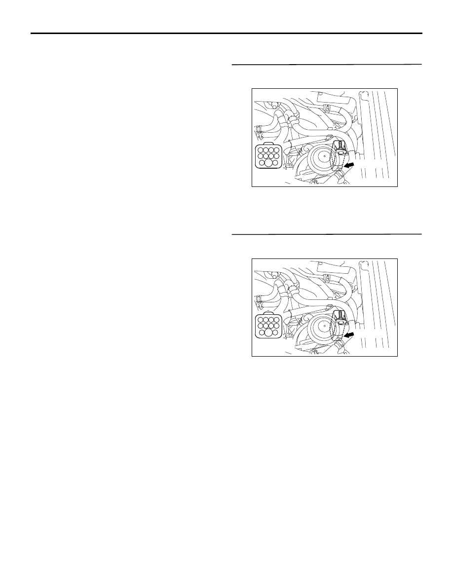
STEP 2. Perform voltage measurement at A-151
glow control unit connector.
• Disconnect connector, and measure at harness
side.
• Ignition switch: ON
• Voltage between terminal No. 6 and earth.
OK: System voltage
Q: Is the check result normal?
YES :
Go to Step 4 .
NO :
Go to Step 3 .
AKB00264
4 3 2 1
8 7 6 5
11 10 9
AB
A-151 (B)
Harness side
connector
Connector: A-151
AKB00264
4 3 2 1
8 7 6 5
11 10 9
AB
A-151 (B)
Harness side
connector
Connector: A-151